http://www.mikrocontroller.net/svnbrowser/transistortester/
Valores de ESR tĂpicos para condensadores (por uF / V)
| Capacidad | 10V | 16V | 25V | 35V | 63V | 160V | 250V |
| 1uF | - | - | 5 | 4 | 6 | 10 | 20 |
| 2.2uF | - | - | 2.5 | 3 | 4 | 9 | 14 |
| 4.7uF | - | - | 6 | 3 | 2 | 6 | 5 |
| 10 uF | - | 1.6 | 1.5 | 1.7 | 2 | 3 | 6 |
| 22 uF | 3 | 0.8 | 2 | 1 | 0.8 | 1.6 | 3 |
| 47 uF | 1 | 2 | 1 | 1 | 0.6 | 1 | 2 |
| 100 uF | 0.6 | 0.9 | 0.5 | 0.5 | 0.3 | 0.5 | 1 |
| 220 uF | 0.3 | 0.4 | 0.4 | 0.2 | 0.15 | 0.25 | 0.5 |
| 470 uf | 0.15 | 0.2 | 0.25 | 0.1 | 0.1 | 0.2 | 0.3 |
| 1000 uF | 0.1 | 0.1 | 0.1 | 0.04 | 0.04 | 0.15 | - |
| 4700 uF | 0.06 | 0.05 | 0.05 | 0.05 | 0.05 | - | - |
| 10000 uF | 0.04 | 0.03 | 0.03 | 0.03 | - | - | - |
An ESR meter (equivalent series resistence) is a two-terminal electronic measuring instrument designed and used primarily to measure the equivalent series resistance (ESR) of real capacitors; usually without the need to disconnect the capacitor from the circuit it is connected to. Most ESR meters work by applying voltage pulses to the capacitor under test which are too short to appreciably charge it; any voltage appearing across the capacitor is due to ohmic drop across the ESR. Measuring ESR can also be done by applying an alternating voltage at a frequency at which the capacitor's reactance is negligible, in a voltage divider configuration.
Other types of meter, including normal capacitance meters, cannot be used to measure a capacitor's ESR, although a few combined meters are available which measure both ESR and out-of-circuit capacitance. A standard (DC) milliohmmeter cannot be used to measure ESR, because a steady direct current cannot be passed through the capacitor.
Most ESR meters can also be used to measure non-inductive low-value resistances, whether or not associated with a capacitor; this leads to a number of additional applications described below.
Need for ESR measurement
Aluminium electrolytic capacitors have a relatively high ESR that increases with age, heat, and ripple current; this can cause the equipment using them to malfunction. In older equipment, this tended to cause hum and degraded operation; modern equipment, in particular switch-mode power supplies, is very sensitive to ESR, and a capacitor with high ESR can cause equipment to malfunction or cause permanent damage requiring repair, typically by causing power supply voltages to become excessively high.[1] This type of capacitor is very often used because it is inexpensive and has a very high capacitance per unit volume or weight; typically, these capacitors have capacitance from about one microfarad to tens of thousands of microfarads.
Capacitors with faults leading to high ESR often bulge and leak, making them easy to identify visually; however, capacitors that appear visually perfect may still have high ESR, detectable only by measurement.
Precise measurement of ESR is rarely necessary, and any usable meter is adequate for troubleshooting. Where precision is required, measurements must be taken under appropriately specified conditions, because ESR varies with frequency, applied voltage, and temperature. A general-purpose ESR meter operating with a fixed waveform is unlikely to be suitable for precise laboratory measurements.
Principles of operation
Most ESR meters work by discharging a real electrolytic capacitor (essentially equivalent to a perfect capacitor in series with an unwanted resistance, the ESR) and passing an electric current through it for a short time, too short for it to charge appreciably. This will produce a voltage across the device equal to the product of the current and the ESR plus a negligible contribution from a small charge in the capacitor; this voltage is measured and its value divided by the current (i.e., the ESR) shown in ohms or milliohms on a digital display or by the position of a pointer on a scale. The process is repeated tens or hundreds of thousands of times a second.
Alternatively an alternating current at a frequency high enough that the capacitor's reactance is much less than the ESR can be used. Circuit parameters are usually chosen to give meaningful results for capacitance from about one microfarad up, a range that covers typical aluminium capacitors whose ESR tends to become unacceptably high.
The ESR considered acceptable depends upon capacitance (larger capacitors usually have lower ESR), and may be read from a table of "typical" values, or compared with a new component. In principle, the manufacturer's upper limit specification for ESR can be looked up in a datasheet, but this is usually unnecessary. When a capacitor whose ESR is critical degrades, power dissipation through the higher ESR usually causes a rapid and large runaway increase, so go/no-go measurement is usually good enough as the ESR rapidly moves from a clearly acceptable to a clearly unacceptable level; an ESR of over a few ohms (less for a large capacitor) is unacceptable.
In a practical circuit, the ESR will be much lower than any other resistance in parallel with the capacitor, so it is not necessary to disconnect the component, and an in-circuit measurement can be made. Practical ESR meters use a voltage too low to switch on any semiconductor junctions that may be present in the circuit, which might present a low "on" impedance that would interfere with measurements.
It is easy to check ESR well enough for troubleshooting by using an improvised ESR meter comprising a simple square-wave generator and oscilloscope, or a sinewave generator of a few tens of kilohertz and an AC voltmeter, using a known good capacitor for comparison, or using a little mathematics.[2] A professional ESR meter is more convenient for checking multiple capacitors in rapid succession on a crowded board.
Other uses
An ESR meter is more accurately described as a pulsed or high-frequency AC milliohmmeter (depending upon type), and it can be used to measure any low resistance. Depending upon the exact circuit used, it may also be used to measure the internal resistance of batteries (many batteries end their useful life largely due to increased internal resistance, rather than low EMF. However, an ESR meter with back-to-back protective diodes across its input cannot be used to measure batteries), contact resistance of switches, the resistance of sections of printed circuit (PCB) track, etc.
While there are specialised instruments to detect short-circuits between adjacent PCB tracks, an ESR meter is useful because it can measure low resistances while injecting a voltage too low to confuse readings by switching on semiconductor junctions in the circuit. An ESR meter can be used to find short-circuits, even finding which of a group of capacitors or transistors connected in parallel by printed circuit tracks or wires is short-circuited. Many conventional ohmmeters and multimeters are not usable for very low resistances, and those that are often use too high a voltage, risking damage to the circuit being tested.
Tweezer probes are useful when test points are closely spaced, such as in equipment made with surface mount technology. The tweezer probes can be held in one hand, leaving the other hand free to steady or manipulate the equipment being tested.
Limitations
- An ESR meter does not measure the capacitance of a capacitor; the capacitor must be disconnected from the circuit and measured with a capacitance meter (or a multimeter with this capability). Excessive ESR is far more likely to be an identified problem with aluminium electrolytics rather than out-of-tolerance capacitance, which is rare in capacitors with acceptable ESR.
- A faulty short-circuited capacitor will incorrectly be identified by an ESR meter as having ideally low ESR, but an ohmmeter or multimeter can easily detect this case, which is much rarer in practice than high ESR. It is possible to connect the test probes to an ESR meter and ohmmeter in parallel to check for both shorts and ESR in one operation; some meters both measure ESR and detect short-circuits.
- ESR may depend upon operating conditions (mainly applied voltage, temperature); a capacitor which has excessive ESR at operating temperature and voltage may test as good if measured cold and unpowered. Some circuit faults due to such intermittent capacitors can be identified by using freeze spray; if cooling the capacitor restores correct operation, it is faulty.
- An ESR meter may be damaged by connection to a capacitor with significant voltage across it, either because of residual stored charge or in a live circuit. Protective diodes across the input will minimise this risk, but then the meter can no longer be used to measure battery internal resistance.
- When an ESR meter is used as a milliohmmeter, any significant inductance present between the test probes will make measurements meaningless. For example, an ESR meter is unsuitable for measuring the resistance of transformer windings because of their inductive characteristics. This effect is significant enough that test probes with coiled cords should not be used due to their inductance.
References
- Jump up ^ Example of high-ESR capacitors causing voltages to rise in a circuit and destroy components. High ESR capacitors cause "5V dropping quite low and causing every other voltage to go sky high (and doing things like frying the HDD with upwards of 15V rather than 12V, and frying the tuning agc transistor with upwards of 36V instead of 30V)."
- Jump up ^ Stephen M. Powell (2000). "99 cent ESR test adapter". Retrieved 2012-03-10.
How to choose an ESR Meter
Why a technician needs an ESR meter
Troubleshooting a circuit requires an investment
in quality equipment. There are no shortcuts.
Without the correct equipment, a hobbyist-tec
hnician could damage your equipment beyond
repair, notwithstanding the fact that he is
incapable of diagnosing the original fault.
Today, a bare minimum of diagnostic equipmen
t is a good-quality oscilloscope, a high-quality
Analog Multimeter, a high-quality Di
gital Multimeter, and an ESR Meter.
Without these 4 basic pieces of equipment, a tec
hnician cannot be considered as serious in the
trade.
I will discuss here the benefits of the ESR meter,
an indispensable tool for taking care of circuit
problems at their source.
Many times, I have received units for repair, in wh
ich the failed part appears to be quite obvious â
a semiconductor transistor or IC. Simple - just
replace the semiconductor and return it to the
customer. But after a few weeks or months, it fails again, resulting in wasted comeback time, and
reduced trust from your customer.
The facts are quite simple â semiconductors are i
nherently very reliable and do NOT just fail willy-
nilly.
There is usually a clear underlying
cause for that failure â heat.
That heat is generated by either:
1.
Insufficient cooling ventilation (a manufacturin
g design fault and beyond the scope of this
article), or much more likely,
2.
Unstable current due to aging capacitors.
So, unless the cause of that semiconductor failure is
taken care of, at the same time that the actual
semiconductor is replaced, there WILL be repeat failures.
The most useful tool for diagnosing failing capacito
rs is the ESR meter. It measures the Equivalent
Series Resistance (the aging capacitor starts to be
have like a resistor, impeding current erratically),
and it measures it In-Circuit, so no ti
me-consuming desoldering is necessary.
A Capacitance Meter is not useful at all in thes
e cases, as a failing capacitor may still show an
acceptable level of capacitance.
I have tried a number of ESR meters on the market,
and this is my objective conclusion as to the
most capable and user-friendly unit for a techni
cian to use. As I write this, I have used these
meters for well over two years on my very-busy te
st-bench, so I can assume with some certainty
that this is how a busy technician is also going
to feel about using these on a day-to-day basis.
Australian Bob Parker pioneered the ESR meter, and
although his original
units are no longer
available, 2 companies licensed his tec
hnology to continue his legacy today.
I evaluated the following units:
1. EVB ESR meter (European-manufactured
licensee of Bob Parker's technology)
2. Anatek Blue ESR meter (USA-marketed â po
ssibly Far-East manufactured licensee of Bob
Parker's technology)
3. PEAK Atlas ESR meter (UK-manufactured SMD desig
www.ebay.com/itm/281237304221 ___________________________________________________________________
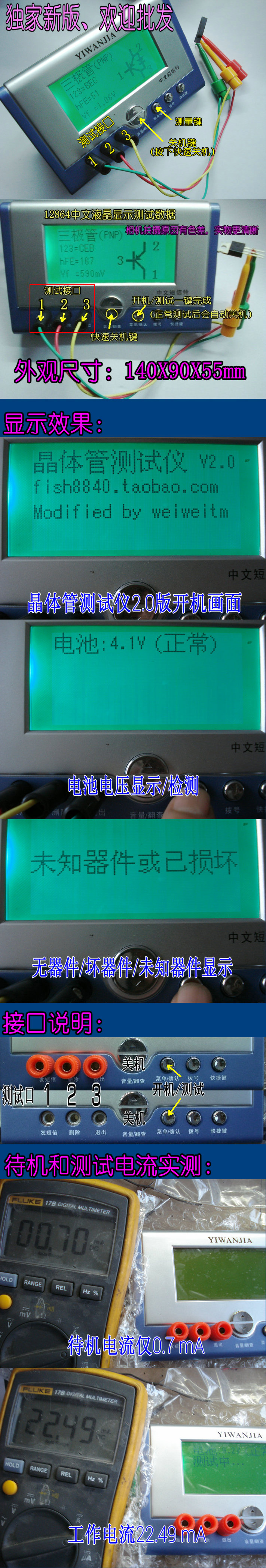
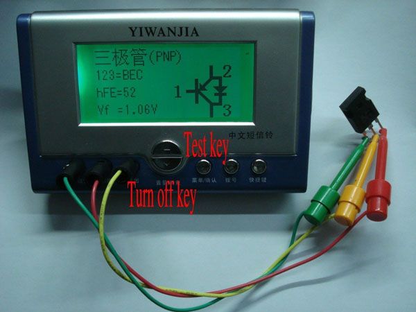
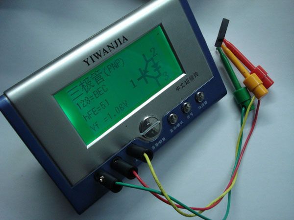
Features:
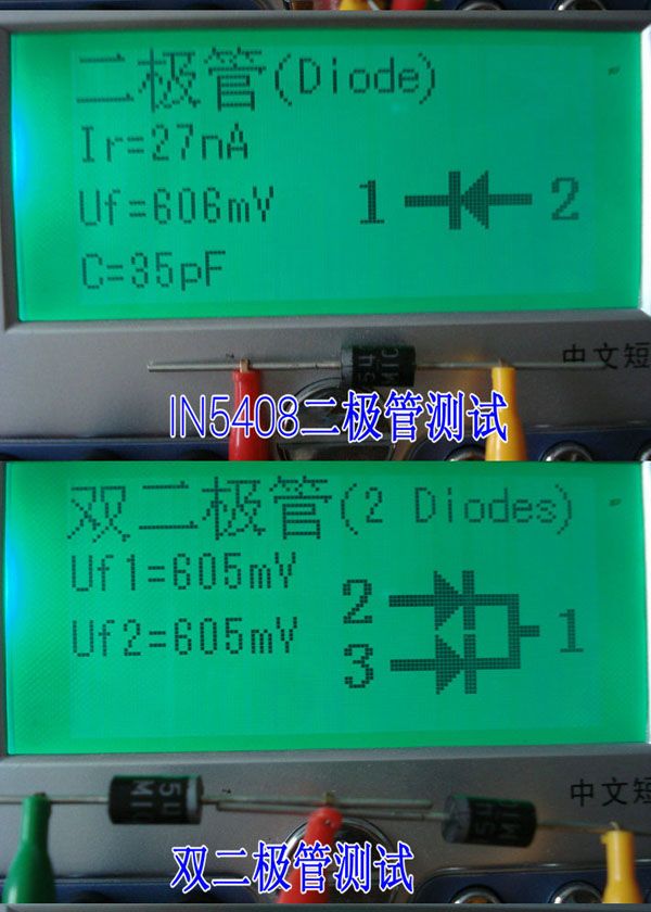
* Graphic display tubes symbols and pin order. Glance.
* Add boot voltage detection function
* Automatic detection of NPN and PNP transistors, N-channel and P-channel MOSFET, diodes (including dual diode), thyristors, transistors, resistors and capacitors and other components,
* Automatic test out the pin element and displayed on the LCD
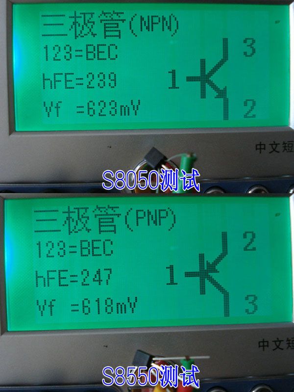
* Can be detected to determine the transistor emitter forward bias voltage of the transistor, MOSFET protection diode and the amplification factor of the base
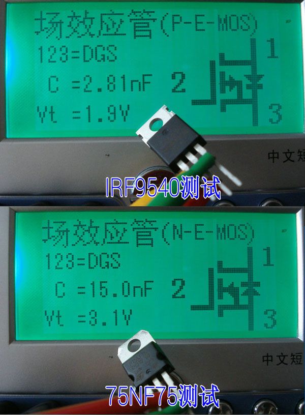
* Measure the gate threshold voltage and gate capacitance of the MOSFET
* 12864 Chinese LCD monitors use (128 * 64 dot dots)
* High test speed, valid component test: 2 seconds (except in the larger capacitor of large capacitance measurement also takes a long time, the measured time of one minute is normal)
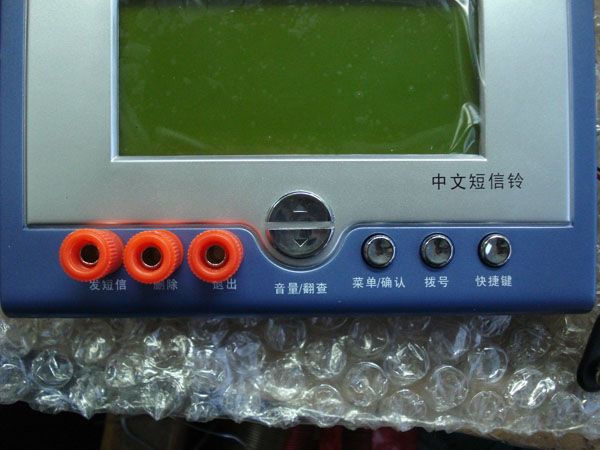
* One button operation, power-on test, get a key.
* Added fast shutdown button.
* Power consumption off mode
* Auto power off function to avoid unnecessary waste, saving battery power, improved battery life.
_______________________________________________________
Corrective steps : Short three test hook into the test , the screen prompts correction steps. When prompted to disconnect short time off the hook three tests . Continue to walk without human intervention. When prompted , please access 100NF 1-3 feet above the capacitor when the access and distribution correction capacitor 105. Then the program will automatically enter the next step. Until the end of the correction restart . The end of the correction.
This is a reference foreigner Markus F ( according to the circuit diagram presumably ) the ATMEGA328 transistor tester program modification . Store the original author weiweitm and shopkeepers from the summer of 2013 the groundbreaking transplant 12864 Chinese LCD screen, increased multi- speed automatic correction procedures , graphical display of the original graphic pin order .
Markus F1602 LCD gives the following version of the instructions for your reference.
1 . Using ATmega8, ATmega168 or ATmega328 microcontroller.
2. 2x16 character LCD display results.
3 . One button operation , automatic power off.
4 . Shutdown current is only 20nA, support battery operation.
5. A low-cost version without the crystal , auto power off. 1.05k ATmega168 or ATmega328 version of the software when no measurement to reduce power consumption in sleep mode .
6. Automatic detection PNP and NPN bipolar transistor , N, P -channel MOSFET, JFET, diodes, dual diode , thyristor SCR.
7 . Automatic detection pin layout.
8. Current amplification factor of bipolar transistors and measuring the threshold voltage emitter junction .
9. Darlington transistor may be identified by the amplification factor of the high threshold voltage and high current .
10. For bipolar transistor , MOSFET protection diode testing.
11. And measuring the threshold voltage of the MOSFET gate capacitance .
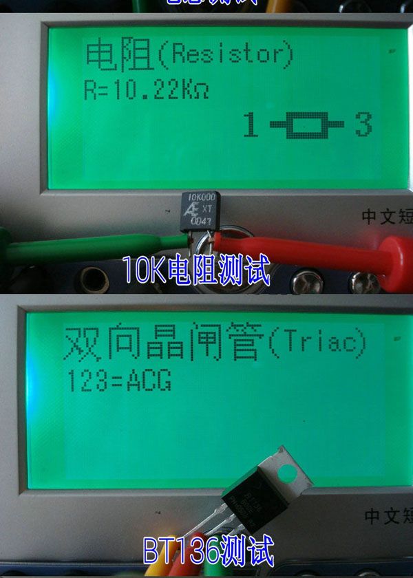
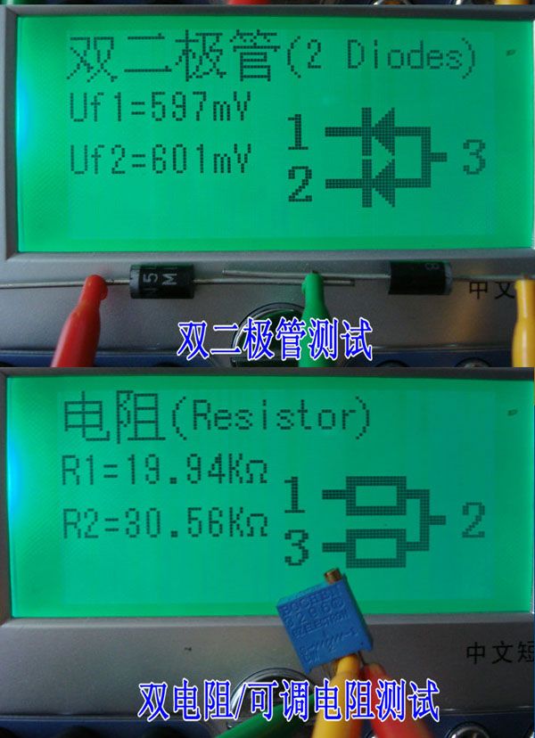
12. Supports two resistance measurements and symbols show the highest four numbers and units. Both ends of the resistor symbol is shown connected to the tester probes number (1-3 ) . Therefore, the potential can also be measured . If the potentiometer is adjusted to its end , the tester can not distinguish the two ends of the pin and the middle .
13. Resistance measurement resolution is 0.1 ohm , the highest measured value 50M ohms.
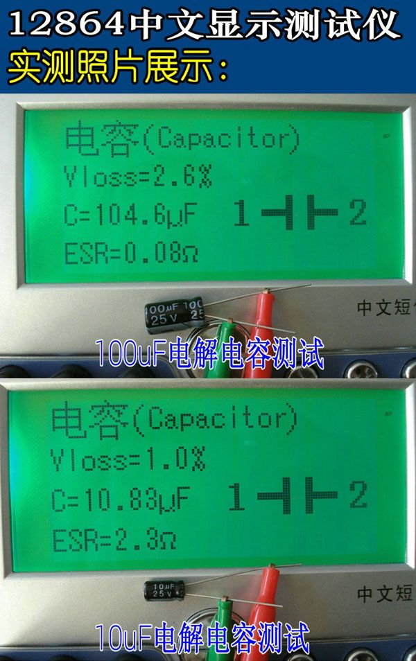
14. Can be detected and measured with a capacitor . Maximum four digits and units. Value can be from 25pf (8MHz clock , 50pF @ 1MHz clock ) to 100mF. Resolution up to 1 pF (@ 8MHz clock ) .
15. For the above values ââcan 2UF capacitor equivalent series resistance (ESR) capacitor value measurements. Resolution of 0.01 ohms and a two-digit numeric display . This feature requires at least 16K Flash ATMEGA (ATmega168 or ATmega328).
16. Two diodes can display symbols in the right direction . Further, the display forward voltage drop.
17. LED detection diode forward voltage drop is much higher than normal. Dual LED detected as double diodes.
18. Zener diode can be detected if the reverse breakdown voltage is less than 4.5V. This is displayed as two diodes , can only be determined by the voltage . Diode symbol is the same around the probe , in this case you can 700mV threshold voltage near real identification diode anode !
19. **** This annual understand , do not turn the ****
If more than three diode -type parts detection, failure to establish the number of diode display another message . This will only happen if the diode is connected to all three probes and at least one diode . In this case , you should only connect the two measuring probe and start again , one by one.
20. Measuring a single diode reverse capacitance value. Bipolar transistors also can measure , if you connect the base and collector or emitter .
21. Only one measurement to find full-bridge connection .
22. Values ââless than 25pf capacitor typically undetectable , but a diode in parallel with 25pf capacitor or at least parallel. In this case , you must subtract the part of the parallel capacitance values.
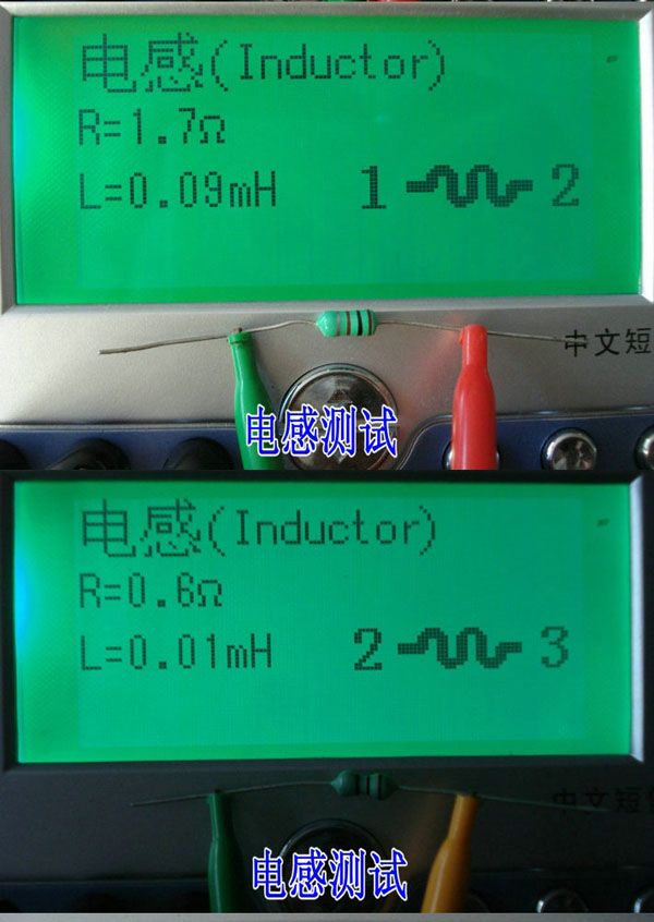
23. Less than 2100 ohm resistor will measure inductance, if you have at least 16K ATMEGA flash . Range from 0:01 mH than 20H, but the accuracy is not good. Measurement results show only a single component connection.
24. Testing time is about two seconds , only capacitance and inductance measurements will take a long time .
25. Software can set the number of measurements before the power is automatically turned off .
26. Built-in self-test function with selectable clock frequency of 50Hz signal to check the accuracy and waits for a call (ATmega168 and ATmega328).
27. Optional internal resistance and zero offset calibration of measuring equipment self-test capability of the output port (ATmega168 and ATmega328). Need a 100nF to 20uF capacitor connected to the compensation between analog comparator pins 1 and 3 of the offset voltage. This can reduce the measurement error than 40uF capacitor . With the same internal calibration capacitor voltage reference voltage to adjust the reference measurements was found inside the ADC gain.
If the test current exceeds the holding current , SCR and triac can be detected. But some current higher than the semiconductor SCR and triac tester can provide the trigger current . Available test current is only about 6mA! Note that all functions have only used single-chip program memory as more ATmega168.
____________________________________________________________
ćèœïŒ
*ćŸćœąæŸç€ș知ć珊ć·ććŒèéĄșćșăäžçźäșç¶ă
*æ°ćąćŒæșç”ćæŁæ”ćèœ
*èȘćšæŁæ”NPNćPNPæ¶äœçźĄïŒNæČéćPæČéMOSFETïŒäșæ知ïŒć
æŹćäșæ知ïŒăæ¶éžçźĄăäžæ知ăç”é»ćšćç”ćźčćšçć
件ïŒ
*èȘćšæ”èŻćșć
件çćŒèïŒćč¶æŸç€șćšæ¶Čæ¶äž
*ćŻä»„æŁæ”æ¶äœçźĄăMOSFETäżæ€äșæ知ççæŸć€§çł»æ°ććșæ°ç祟ćźćć°ææ¶äœçźĄçæŁććçœźç”ć
*æ”éæ
æéćŒç”ććæ
ç”ćźčçMOSFET
*æŸç€șćšäœżçš12864äžææ¶Čæ¶ïŒ128*64äžȘçčé”çčç»æïŒ
*èŸé«çæ”èŻéćșŠïŒæææç»ä»¶æ”èŻïŒćš2ç§ïŒé€ćšèŸć€§çç”ćźčćšïŒć€§ç”ćźčçæ”éèżéèŠèŸéżæ¶éŽïŒæ”éçæ¶éŽäžș1ćéæŻæŁćžžçïŒ
*äžéźæäœïŒćŒæșæ”èŻïŒäžéźæćźă
*æ°ćąćż«éć
łæșæéźă
*ćçæ¶èć
łéæšĄćŒ
*èȘćšć
łæșćèœïŒćŻä»„éżć
äžćż
èŠçæ”ȘèŽčïŒèçșŠç”æ± èœéïŒæé«ç»èȘæ¶éŽă

ç«æŁæ„éȘ€ïŒçè·ŻäžäžȘæ”èŻćŸïŒèżć
„æ”èŻïŒć±ćčæç€șæ ĄæŁæ„éȘ€ăćœæç€șæćŒçæ„æ¶ćæćŒäžäžȘæ”èŻćŸă继ç»è”°æ éäșșäžșćčČéąăćœæç€șèŻ·ćš1-3èæ„ć
„100NF仄äžç”ćźčæ¶ćïŒæ„ć
„é
éçç«æŁç”ćźč105.äčćçšćșäŒèȘćšèżć
„äžäžæ„ăçŽć°ç«æŁç»æéćŻăç«æŁç»æ.
èżäžȘæŻćéŽèć€Markus FïŒæ čæźç”è·ŻćŸæšæ”ïŒçATMEGA328çæ¶äœçźĄæ”èŻä»Șçšćșäżźæčăćșć
ćèŁ
äœè
weiweitmććșäž»ä»2013ćčŽæććŒć§ćšćïŒç§»æ€12864äžææ¶Čæ¶ć±ïŒćąć ć€æĄŁèȘćšæ ĄæŁçšćșïŒćŸćœąćæŸç€șć件ćŸćœąćŒèéĄșćșă
äžéąç»ćșMarkus F1602æ¶Čæ¶æŸç€șçæŹçèŻŽæäŸć€§ćź¶ćèă
1ăéçšATmega8ïŒATmega168æATmega328ćŸźæ§ć¶ćšă
2ă2x16ć珊æ¶Čæ¶æŸç€șćšæŸç€șç»æă
3ăäžéźæäœïŒèȘćšć
łéç”æșă
4ăć
łæç”æ”ćȘæ20nAïŒæŻæç”æ± æäœă
5ăäœææŹççæŹäžçšæ¶æŻïŒæŻæèȘćšć
łéç”æșă1.05kçæŹèœŻä»¶çATmega168æATmega328ćšæČĄææ”éæ¶çšçĄç æčćŒæ„éäœç”æșæ¶èă
6ăèȘćšæŁæ”PNPćNPNććææ¶äœçźĄïŒNăPæČéMOSFETïŒJFETïŒäșæ知ïŒćäșæ知ïŒæ¶éžçźĄćŻæ§çĄ
ă
7ăèȘćšæŁæ”ćŒèćžć±ă
8ăæ”éćæćæ¶äœçźĄçç”æ”æŸć€§çł»æ°ććć°ç»çéćŒç”ćă
9ă蟟æ饿æ¶äœçźĄćŻä»„éèżé«éćŒç”ććé«ç”æ”æŸć€§çł»æ°èŻć«ă
10ăćŻčćæćæ¶äœçźĄïŒMOSFETçäżæ€äșæ知çæŁæ”ă
11ăæ”éMOSFETçéćŒç”ććæ
æç”ćźčćŒă
12ăæŻæ䞀äžȘç”é»çæ”éć珊ć·æŸç€șïŒæé«ćäœæ°ćććäœæŸç€șăæŸç€șçç”é»çŹŠć·äž€ç«ŻæŻèżæ„çæ”èŻä»ȘæąéçŒć·ïŒ1-3ïŒăæ仄ç”äœćšäčćŻä»„æ”éăćŠæç”äœćšè°æŽć°ćźçäžç«ŻïŒæ”èŻä»Șäžèœć蟚äžéŽć䞀端çćŒèă
13ăç”é»æ”éçć蟚çæŻ0.1æŹ§ć§ïŒæé«æ”éćŒ50MæŹ§ć§ă
14ăćŻä»„èą«æŁæ”ćæ”éäžäžȘç”ćźčćšăæé«ćäœæ°ćććäœæŸç€șăæ°ćŒćŻä»„æŻä»25pfïŒ8MHzæ¶éïŒ50pF@ 1MHzçæ¶éïŒć°100mFăć蟚çćŻèŸŸ1 pFïŒ@ 8MHzæ¶éïŒă
15ăćŻä»„ćŻčäș2UFæ°ćŒä»„äžçç”ćźčćšççæäžČèç”é»ïŒESRïŒç”ćźčćŒæ”éăć蟚çäžș0.01æŹ§ć§ćæŸç€ș䞀äœæ°æ°ćŒăæ€ćèœèŠæ±èłć°16KéȘćATMEGAïŒATmega168æATmega328ïŒă
16ăćŻä»„ćŻč䞀äžȘäșæ知æŸç€șæŁçĄźæčćç珊ć·ăæ€ć€ïŒæŸç€șæŁććéă
17ăLEDæŁæ”äžșäșæ知ïŒæŁććéæŻæŁćžžé«ćŸć€ăććć
äșæ知æŁæ”äžșćäșæ知ă
18ăéœçșłäșæ知ćŻä»„èą«æŁæ”ć°ïŒćŠæććć»ç©żç”ćäœäș4.5Văèżć°æŸç€șäžș䞀äžȘäșæ知ïŒćȘèœéèżç”ć祟ćźăæąć€ŽćŽç»äșæ知ç珊ć·æŻçžćçïŒćšèżç§æ
ć”äžïŒäœ ćŻä»„éèż700mVéèżçéćŒç”ćèŻć«äșæ知çæŁçéłæïŒ
19ă****èżæĄæŻćčŽæçœïŒäžçż»äș****
ćŠæè¶
èż3äžȘäșæ知类é¶ä»¶æŁæ”ïŒć»șç«äșæ知æ°çźæŸç€șćŠć€ć€±èŽ„çæ¶æŻăèżćȘäŒćçïŒćŠæäșæ知èżæ„ć°ææçäžæąéćèłć°æäžäžȘæŻćäșæ知ăćšèżç§æ
ć”äžïŒäœ ćșèŻ„ćȘèżæ„䞀äžȘæąéććŻćšæ”éćæŹĄïŒäžäžȘæ„äžäžȘă
20ăæ”éćäžȘäșæ知ććççç”ćźčćŒăćæćæ¶äœçźĄäčèżćŻä»„æ”éïŒćŠæäœ èżæ„ćșæäžéç”ææćć°æă
21ăćȘéèŠäžæŹĄæ”éæŸćșć
šæĄ„çèżæ„ă
22ăæ°ćŒäœäș25pfç”ćźčćšéćžžæŁæ”äžć°ïŒäœćŻä»„äžäžäžȘäșæ知ćč¶èæèłć°25pfç”ćźčćšćč¶èăćšèżç§æ
ć”äžïŒäœ ćż
饻ćć»ćč¶èç”ćźčćŒçéšćă
23ăç”é»äœäș2100æŹ§ć§äŒæ”éç”æïŒćŠæäœ çATMEGAèłć°ć
·æ16KéȘćăèćŽć°ä»0:01mHè¶
èż20HïŒäœçČŸćșŠäžć„œăæ”éç»æćȘæŸç€șćäžć
件èżæ„ă
24ăæ”èŻçæ¶éŽæŻć€§çșŠäž€ç§éïŒćȘæç”ćźčćç”ææ”éäŒéèŠèŸéżçæ¶éŽă
25ăèœŻä»¶ćŻä»„èźŸćźç”æșèȘćšć
łéćçæ”éæŹĄæ°ă
26ăć
ć»șèȘæŁćèœäžćŻéç50Hz俥ć·æŁæ„çæ¶ééąçć祟æ§ćçćŸ
è°çšïŒATmega168ćATmega328ïŒă
27ăćŻéèźŸć€æ Ąćç«ŻćŁèŸćșçć
é»ćé¶ć€±è°èȘæŁèœćçæ”éïŒATmega168ćATmega328ïŒăéèŠäžäžȘ100nFć°20uFç”ćźčèżæ„ć°ćŒè1ććŒè3äčéŽèĄ„ćżæšĄææŻèŸćšç怱è°ç”ćăèżćŻä»„ćć°40uF仄äžç”ćźčćšçæ”éèŻŻć·źăçšçžćçç”ćźčćšć
éšæ ĄæŁç”ććèç”ćèą«ćç°è°æŽć
éšćèæ”éADCçćąçă
ćŠææ”èŻç”æ”è¶
èżç»Žæç”æ”ïŒćŻæ§çĄ
ććććŻæ§çĄ
ćŻä»„èą«æŁæ”ć°ăäœæŻäžäșććŻŒäœćŻæ§çĄ
ććććŻæ§çĄ
æŻèŻ„æ”èŻä»ȘèœæäŸçç”æ”æŽé«ç觊ćç”æ”ăćŻæäŸçæ”èŻç”æ”ä»
çșŠ6mAïŒæłšæïŒææćèœä»
çšäșææŽć€ççšćșććšćšçćçæșćŠATmega168ă
___________________________________________________________________
Features:
-
1,2013 latest M328 version of the software ,more functions.
2,Use 8MHz external crystal , better measurement accuracy.
3.Backlight LCD display,only 2mA when stand by.
4,Mainchip is the DIP, easy to DIY, update the mainchip .
5,Using 9V battery (Not inlcuded) Need open sheel then install battery
NEW Function:
1:Automatic detection of NPN and PNP transistors, n-channel and p-channel MOSFET, diode (including double diode), thyristor, transistor, resistor and capacitor and other components
2: Automatic test the pin of a component, and display on the LCD
3:Can detect the transistor, MOSFET protection diode amplification coefficient and the base to determine the emitter transistor forward biased voltage
4: Measure the gate and gate capacitance of the MOSFET threshold voltage
5:Use 12864 Chinese liquid crystal display with green backlight
Size:140*90*55MM
Specifications: For you reference
1,One -button operation, automatic shutdown .
2,Only 20nA shutdown current.
3,Automatically detect NPN, PNP bipolar transistors , N -channel and P -channel MOS FET, JFET , diodes , two diodes, thyristors small power unidirectional and bidirectional thyristor.
4,Automatic identification components pin arrangement .
5,Measuring bipolar transistor current amplification factor and base - emitter threshold voltage.
6,Via the base - emitter threshold voltage and high current amplification factor to identify Darlington transistors.
7,Can detect bipolar transistors and MOS transistors protection diodes.
8,Measuring the gate MOS FET threshold voltage and the gate capacitance.
9,Can simultaneously measure two resistors and resistor symbol is displayed. Displayed on the right with a decimal value of 4 . Resistance symbol on both sides shows the pin number. So you can measure the potentiometer. If the potentiometer wiper is not transferred to an extreme position , we can distinguish the middle and both ends of the pin.
10,Resistance measurement resolution is 0.1 ohms , 50M ohms can be measured .
11,Can measure capacitanceCan measure capacitance of 30pF-100mF , resolution 1pF.
12.2uF more capacitors can simultaneously measure the equivalent series resistance ESR values. The two can be displayed with a decimal value , resolution 0.01 ohms.
13,Can be in the correct order and the diode symbol display two diodes, and gives the diode forward voltage.
14.LED is detected as a diode forward voltage higher . Combo of the LED is identified as two diodes.
15,Reverse breakdown voltage is less than 4.5V Zener diode can be identified.
16,Can measure a single diode reverse capacitance. If the bipolar transistor connected to the base and collector or emitter of a pin , it can measure the collector or emitter junction reverse capacitance .
18 can be obtained with a single measurement rectifier bridge connection.
Notice: Before measuring capacitance , the capacitor must be discharged , otherwise very likely damage the meter .
|
|
|
| Description: |
- Features:
1,2013 latest M328 version of the software ,more functions.
2,Use 8MHz external crystal , better measurement accuracy.
3.Backlight LCD display,only 2mA when stand by.
4,Mainchip is the DIP, easy to DIY, update the mainchip .
5,Using 9V battery (Not inlcuded) Need open sheel then install battery
NEW Function:
1:Automatic detection of NPN and PNP transistors, n-channel and p-channel MOSFET, diode (including double diode), thyristor, transistor, resistor and capacitor and other components
2: Automatic test the pin of a component, and display on the LCD
3:Can detect the transistor, MOSFET protection diode amplification coefficient and the base to determine the emitter transistor forward biased voltage
4: Measure the gate and gate capacitance of the MOSFET threshold voltage
5:Use 12864 Chinese liquid crystal display with green backlight
Size:140*90*55MM
Specifications: For you reference
1,One -button operation, automatic shutdown .
2,Only 20nA shutdown current.
3,Automatically detect NPN, PNP bipolar transistors , N -channel and P -channel MOS FET, JFET , diodes , two diodes, thyristors small power unidirectional and bidirectional thyristor.
4,Automatic identification components pin arrangement .
5,Measuring bipolar transistor current amplification factor and base - emitter threshold voltage.
6,Via the base - emitter threshold voltage and high current amplification factor to identify Darlington transistors.
7,Can detect bipolar transistors and MOS transistors protection diodes.
8,Measuring the gate MOS FET threshold voltage and the gate capacitance.
9,Can simultaneously measure two resistors and resistor symbol is displayed. Displayed on the right with a decimal value of 4 . Resistance symbol on both sides shows the pin number. So you can measure the potentiometer. If the potentiometer wiper is not transferred to an extreme position , we can distinguish the middle and both ends of the pin.
10,Resistance measurement resolution is 0.1 ohms , 50M ohms can be measured .
11,Can measure capacitanceCan measure capacitance of 30pF-100mF , resolution 1pF.
12.2uF more capacitors can simultaneously measure the equivalent series resistance ESR values. The two can be displayed with a decimal value , resolution 0.01 ohms.
13,Can be in the correct order and the diode symbol display two diodes , and gives the diode forward voltage.
14.LED is detected as a diode forward voltage higher . Combo of the LED is identified as two diodes.
15,Eeverse breakdown voltage is less than 4.5V Zener diode can be identified.
16,Can measure a single diode reverse capacitance. If the bipolar transistor connected to the base and collector or emitter of a pin , it can measure the collector or emitter junction reverse capacitance .
18 can be obtained with a single measurement rectifier bridge connection.
Notice: Before measuring capacitance , the capacitor must be discharged , otherwise very likely damage the meter .
- Package Contents
100% Brand New
NEW Transistor Tester Diode Triode Capacitance ESR resistance Meter MOS PNP NPN
|
|