
La vaca cega desconfiada
_FRASE_TOP
| 27-12-2014 (3681 ) | Categoria: ESR |
Switch mode power supplies (SMPS) are now standard for the majority of our home appliances. Old fashioned linear power supplies based on mains frequency transformers are disappearing, mainly because of their cost, their large size and weight. We're taking here about mains voltage (say 120Â V or 230Â V AC) power supplies with power ranging from a few Watts to several hundred Watts.

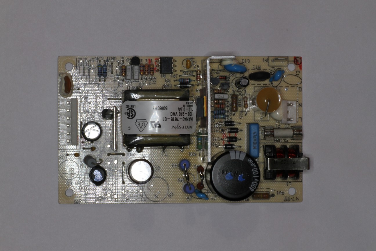
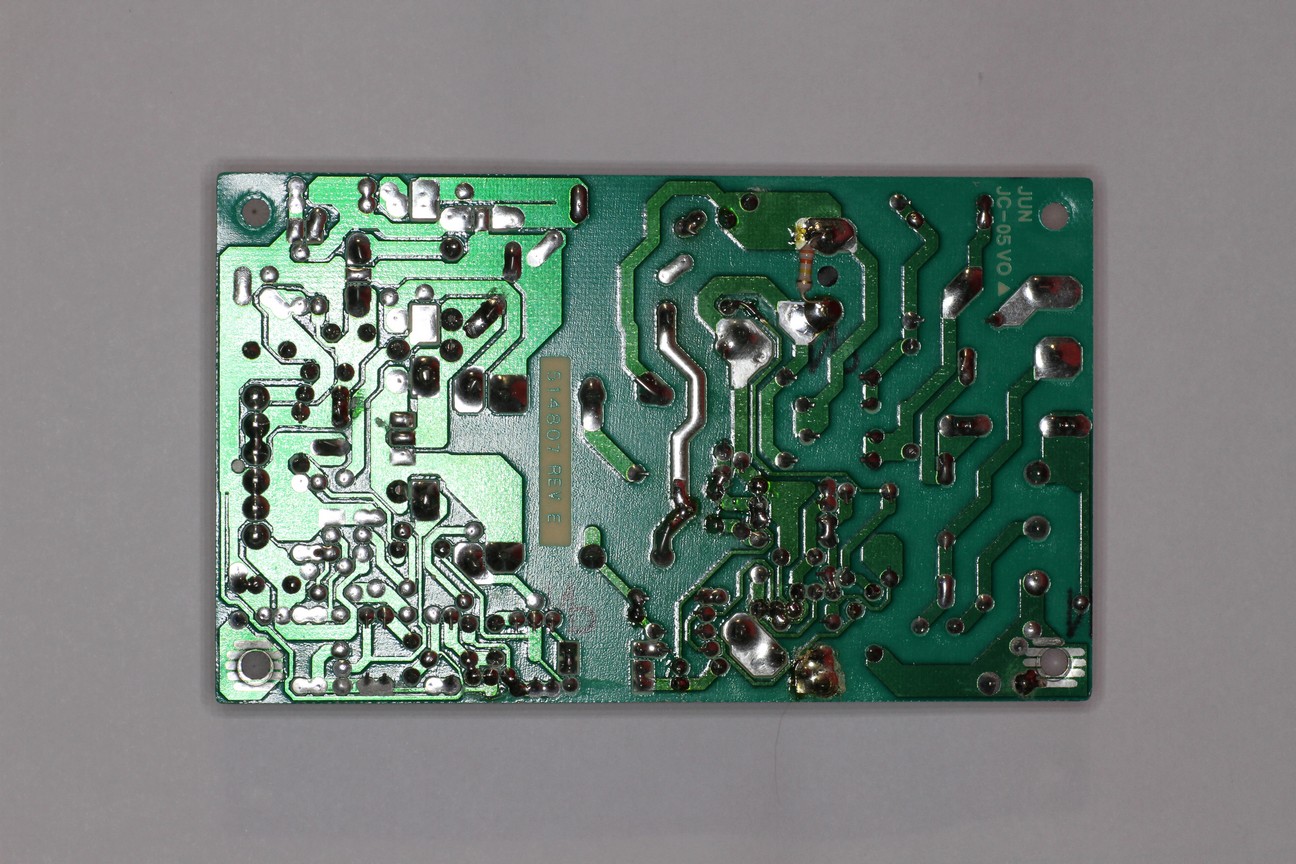
Switch mode power supplies are everywhere; here are some pictures of their guts. The big high power components and small heat sinks are typical of SMPS.
These devices are incredibly reliable, but being very often left powered all the time (even when their load is switched off), they still are the weak link. Components are fed with high voltage, they get warm, they age quickly because of the full time operation and when there is a surge, the SMPS is the first stage concerned. Many problems with our home appliances are due to SMPS faults.
Unfortunately, SMPS are a bit tricky to repair and I often get asked for advice. So, I summarized in this page the basic ideas and the tricks that I use the most.
Here, I suppose you have a perfectly designed circuit that used to work perfectly and suddenly failed. If you're trying to debug your own design, still some of these tricks apply, but you'll probably need much more than just this article.
First, let's take a look to the generic block diagram of a SMPS. The mains power enters the circuits through a line filter, it's rectified and smoothed out to obtain a high DC voltage (a few hundreds volts). Some rectifiers have a switch that makes them a voltage doubler when working with 120Â V AC mains or just a rectifier when working with 230Â V. Some others are designed to work from say 100 to 240Â V AC with no switches and the regulator does the rest. This high DC voltage is switched by one or more transistors (or MOSFETs) to drive the primary of a ferrite transformer. On the secondary side, the voltage is rectified and filtered. Switching transistors are driven by a control circuit that senses the output voltage (and input current) and regulates accordingly. This control circuit is very often on the primary side and often powered by an extra winding on the transformer. A sample of the output voltage is fed back via an opto-coupler. In some cases the control circuit is located on the secondary side and drives the transistor(s) via a small additional transformer. All configurations have some additional circuit to allow the controller to start at power-up.
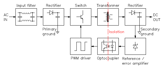
Structure of a SMPS.
There is always a very clear separation between the high and low voltage sides (primary and secondary sides). You can observe it on the bottom (copper) side of the PCB as a larger spacing in the tracks. Some times the solder mask varnish is removed in this area or there are holes and slots to increase insulations. On the pictures in this page, this separation is often marked with a dashed red line.

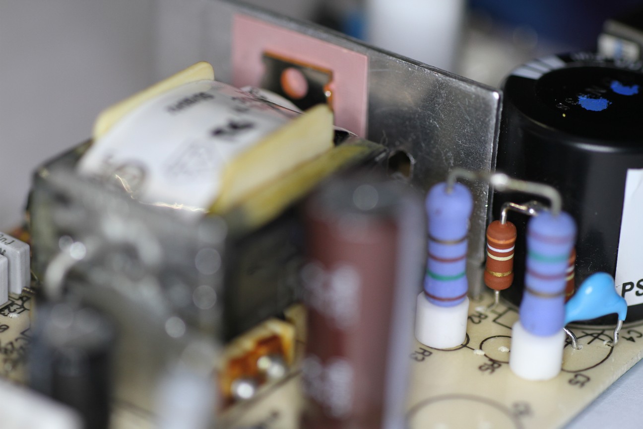
This SMPS uses classic-style (through hole) components. The high voltage side is on the left of the dashed red line.
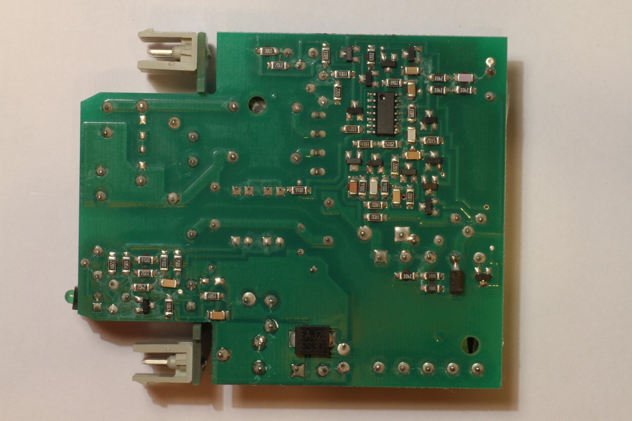
This SMPS uses modern surface mount (SMD) components. Here, the controller uses SMD technology and is mounted on the bottom side. The large SMD diode is the low voltage rectifier. The high voltage side is above the dashed red line.
The primary and secondary side are fully DC isolated by the transformer. Very often, if the ground of the output is not connected to the mains ground, a small high voltage capacitor connects these two grounds at high frequency.
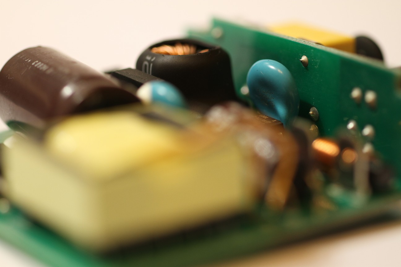
The light blue capacitor in this picture is the high voltage capacitor connecting the low voltage ground with the mains ground. Of course, there is DC insulation.
Before starting, I just want to remind that SMPS are dangerous circuits: half of the components are directly connected to the mains voltage. A large storage capacitor is charged at high voltage and can be dangerous even when the mains supply is disconnected. Not all SMPS include bleeding resistors (or they could be broken) so the capacitors could stay charged for a long time. Always make sure all capacitor are completely discharged before touching the circuit. To discharge the capacitors, don't short them with the screwdriver, use a suitable resistor instead (a few kΩ and a few Watts) connected to two insulated probes like the one of a multimeter. Then, measure the voltage and make sure it's zero before proceeding. Keep also in mind that heat sinks very often are not grounded and they can very well be at mains voltage. Beware of taking measures with an oscilloscope: oscilloscopes are grounded to the mains supply (and it's a bad idea to float them) and you could make a short with your ground lead (this would be dangerous also for your oscilloscope). In summary, SMPS repair is for experienced and skilled technicians; if you don't know exactly what you're doing, stay away from SMPSs.
This SMPS has no bleeder resistor on the high voltage filter capacitor. Please remark the 330 kΩ resistor tack soldered on the bottom side of the PCB during the repair operation to automatically discharge the capacitor in a reasonable time and avoid potential shocks. The high voltage side is on the right of the dashed red line.
I usually start with a visual inspection to get an idea. Of course, first I disconnect the SMPS and I make sure all capacitor are discharged. Many faulty electrolytic capacitors, when not exploded, can easily be spotted because they "inflate" and their top (or bottom) side becomes dome-shaped (see below). Burned resistor can also be spotted by their black colour and bad smell. A look to the ferrite transformer is very important: if it looks burned out and smells badly, I generally give up because it may have shorted turns and it's a nightmare to repair or find a replacement part. If the transformer is faulty, I prefer to replace the whole SMPS and save a lot of time. Some components are warm and as time goes by they tend to get a little brownish (the same is true for the board near them): this is not necessarily a problem; a little brown is ok, black and smelly is not.
If your SMPS has a regulator IC, try to find it's datasheet on the internet: many SMPS have a schematic diagram very similar to the examples reported in the datasheets. If it does, you'll save a lot of time.
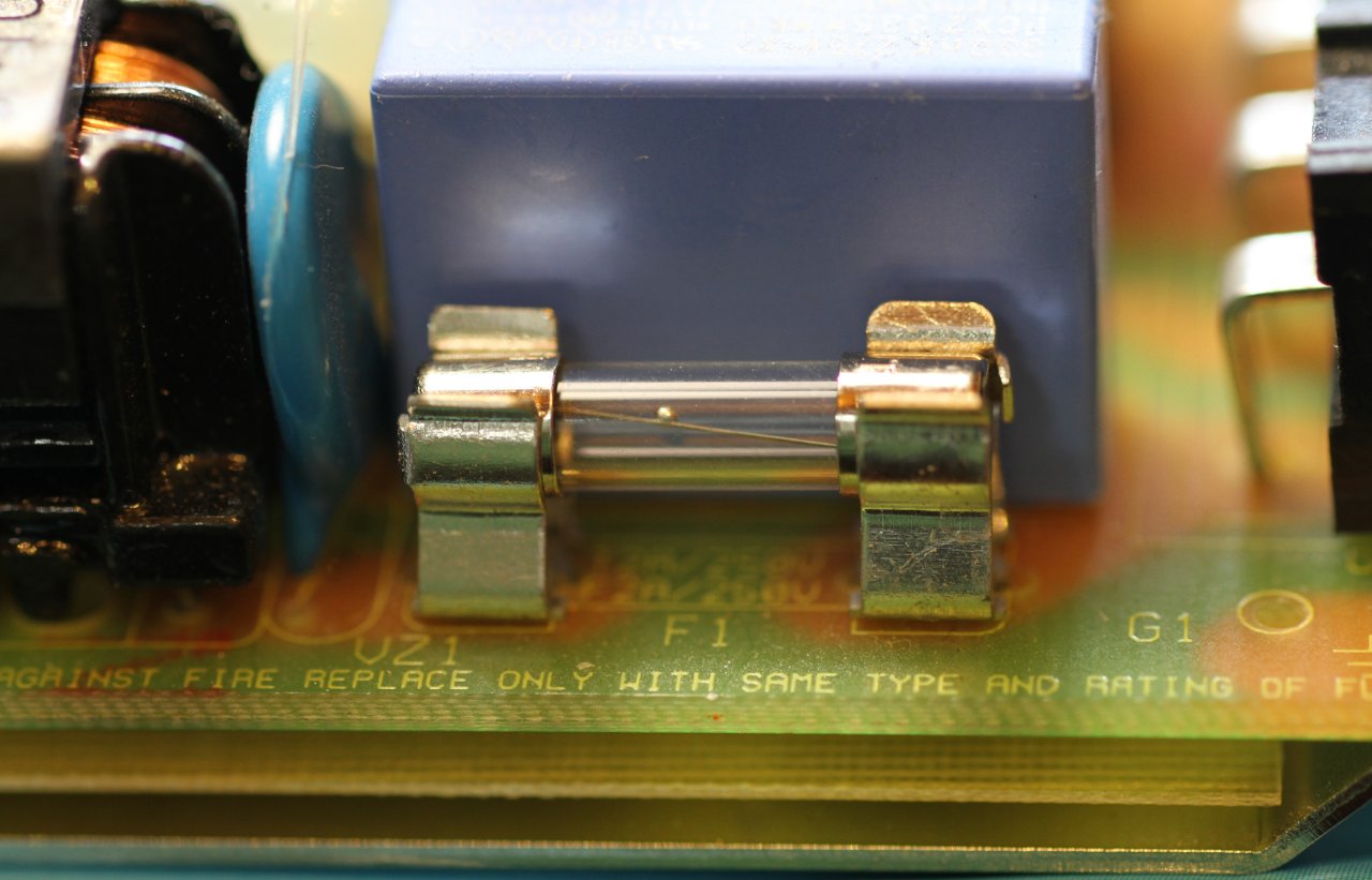
Start by looking at the SMPS mains line fuse (this one is good).
Start by looking at the mains fuse: this will give you good clues on the origin of the failure. A blown fuse usually means many faulty semiconductors; a healthy one is probably just a single component.

Three Ă˜5 × 20 mm fuses: the one on the left is good, the one in the middle blew up with a moderate current and the one on the right blew up with a large current.
Also look at how the fuse looks like: if it only slowly burned the failure was not catastrophic, but if the fuse almost "exploded", there was a big current when it blew up and you can expect a lot of damaged components (especially semiconductors). It doesn't mean you can't fix it, but just that you'll have many components to replace: if you find just a faulty one, you should check again. Unfortunately some fuses are filled with sand and you cannot see what happened.
SMPS can fail in many different ways, the most common being no output power at all. In this case, I start by checking the input fuse. If the fuse is good but there is no output, probably all the semiconductors are good and it could be easy to fix. Keep in mind that usually semiconductors blow up shorted and resistors (and often capacitors) blow up open.
A good candidate is the inrush current limiter (an NTC). Than I check for high power rating resistors, particularly on the primary side: I measure their resistance one by one, in circuit. If the value doesn't match what written (or colour coded) on the component, I unsolder one terminal and measure again: if the value is wrong, I replace it with a new one.
The first resistors to check are the one in series with the power transistors, usually less than one Ohm. Sometimes the regulator is powered by a high value high wattage resistor in series with a Zener diode: if the resistor is good, maybe the Zener is shorted, so I check all diode junctions with the diode function of the multimeter (most of the times, you can do this in circuit). Than I check the capacitors (see below). Faulty regulators IC can happen but it's not very common.
On the other hand, if the fuse is open, than something went really wrong in the circuit. Don't replace the fuse yet, it would just blow again: there is a short circuit somewhere that you have to fix first. Typical problems are blown up power transistors or rectifier diodes, especially on the primary side. Just use the diode function of a multi-meter and check the junctions: shorts are easy to spot. More components can be faulty at the same time and if you don't replace them all, they may blow again, so be careful. Than, I also check for faulty resistors as above and faulty capacitors (see below).
If the power transistor (or one of them) is dead, chances are that many other components are dead too. Often SMPS include protection components such as additional resistor or Zener diodes to reduce damages in case of failure, but not always. Before going to far in replacing, make sure you check all the parts. For example, check if the controller IC still works. Powering it off-line with a small external DC power supply and checking for pulses on the transistor base (or gate) is a good idea. But some IC won't work if there is no high voltage to switch: check the datasheet first. If too many components are dead, it’s probably easier to replace the whole SMPS.
When replacing semiconductors I first try to source the exact same part. If it's unavailable (or too expensive) I look for alternatives. Of course the new semiconductor must show at least the same voltage, current and power characteristics, or be even better. For diodes also check the switching time: you want a diode that is at least as fast as the old one, or faster. For transistor, check the gain and the cut-off frequency: you want a similar gain (not too low and not too high) and a cut-off frequency at least ten times higher than the switching frequency. For MOSFETs check the gate capacitance that should not exceed the one of the old component and the gate threshold voltage that has to be similar to the old device.
After replacing the faulty components, it's a very good idea to use the light bulb trick (see below) for the very first power on test: this will limit the damages in case the problem isn't completely fixed.
Sometimes the SMPS is only partially working: it may start for a fraction of a second and than shut down, or it may pulsate trying to start every few seconds and shutting down after a fraction of a second, or it may produce a wrong output voltage. Here, probably all power semiconductors are good, so the first thing to check are the capacitors (see below).
Than, there may be something wrong with the feedback circuit: a good trick is to apply an external adjustable DC voltage to the SMPS output (the SMPS being not connected to the mains). When gradually increasing the DC voltage, you should see the feedback circuit working when you cross a threshold near the nominal output voltage. Since, while doing this test there are no dangerous voltages involved, you can easily use an oscilloscope to diagnose the feedback circuit. You may also have to supply the controller IC (on primary side) with the same low voltage source to see what happens on the other side of the optocoupler.
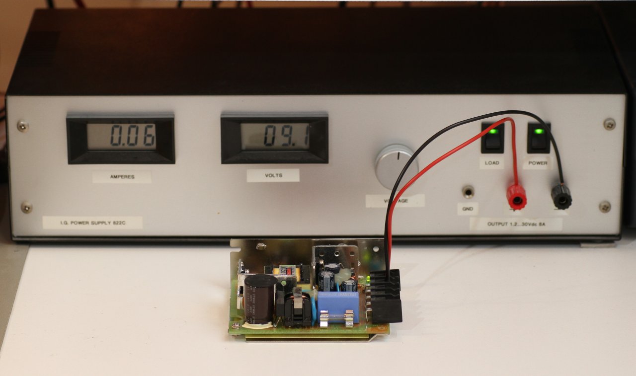
A SMPS being powered on its output by an external laboratory DC power supply to check the feedback circuit.
Â
Electrolytic capacitors are very often the cause of SMPS problems. In cheap designs, where thermal dissipation is a bit too close to the limit, and a choice of components a bit too cost-oriented, electrolytic capacitors are real time-bombs that will eventually fail (sometimes by literally exploding)... The liquid electrolyte inside these components tends to evaporate and dry out completely altering the characteristics.
The two blue electrolytic capacitors in this picture are the low voltage filter capacitors. These ones are in good shape.
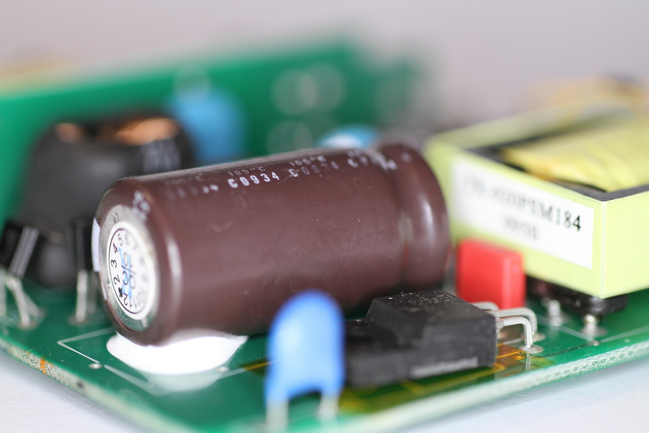
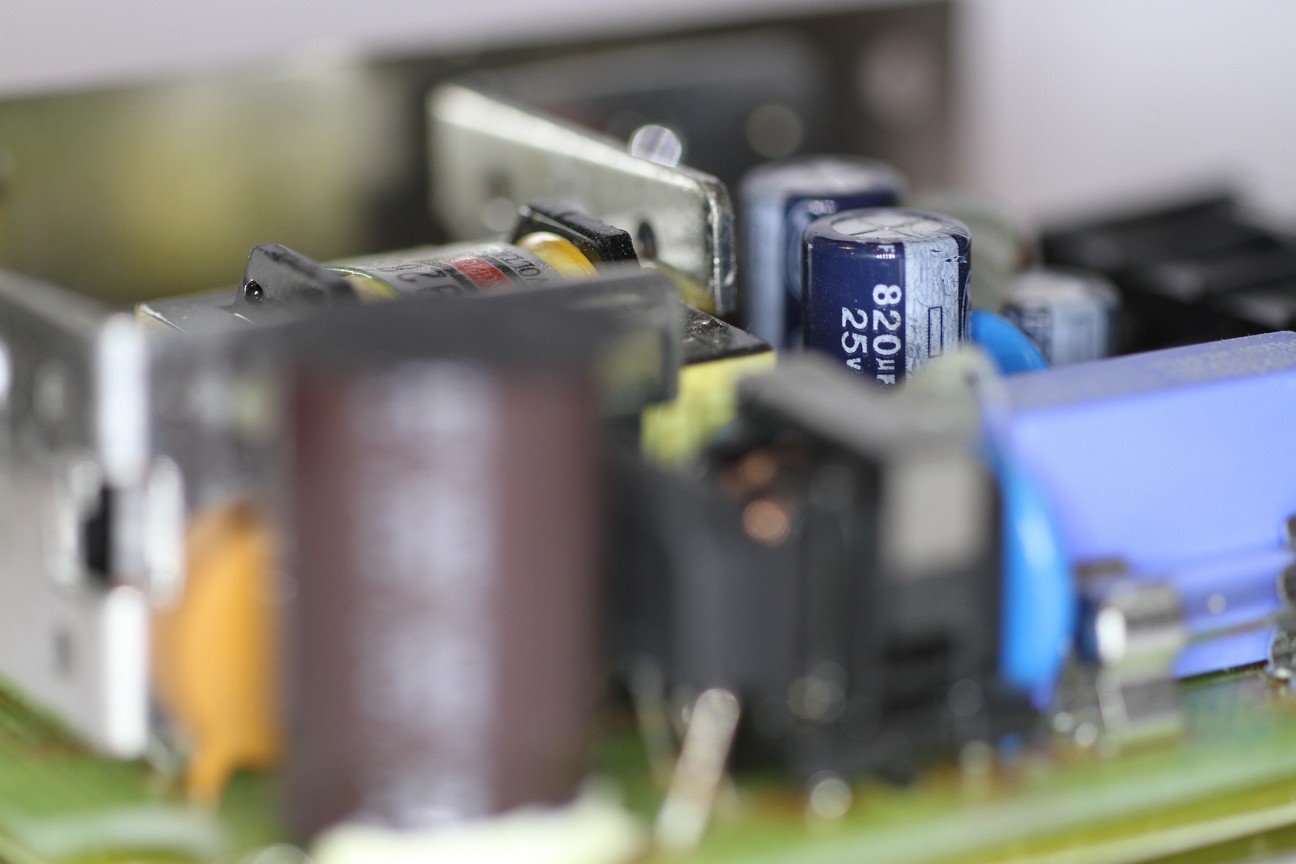
The big brown electrolytic capacitor in this picture is the high voltage filter capacitor. This one is in good shape.
When electrolytic capacitors explode, they throw out corrosive (and bad smelling) projections. The exploded components are easy to spot, but before going any further, one should check the status of the rest of the circuit: if it cannot be cleaned or is already too corroded, replacing the whole SMPS is the best option since corroded components or copper PCB tracks will eventually fail.
Fortunately, only very few electrolytic capacitors explode, the majority of them just fail silently. Look at all the capacitors, their shape and their neighbourhood. If they are not cylindrical anymore, are "inflated", have a dome-shaped top or bottom side (instead of being flat) or have leaked they're faulty. Don't bother measuring them: if it's visually bad it's 100% faulty and needs replacement.
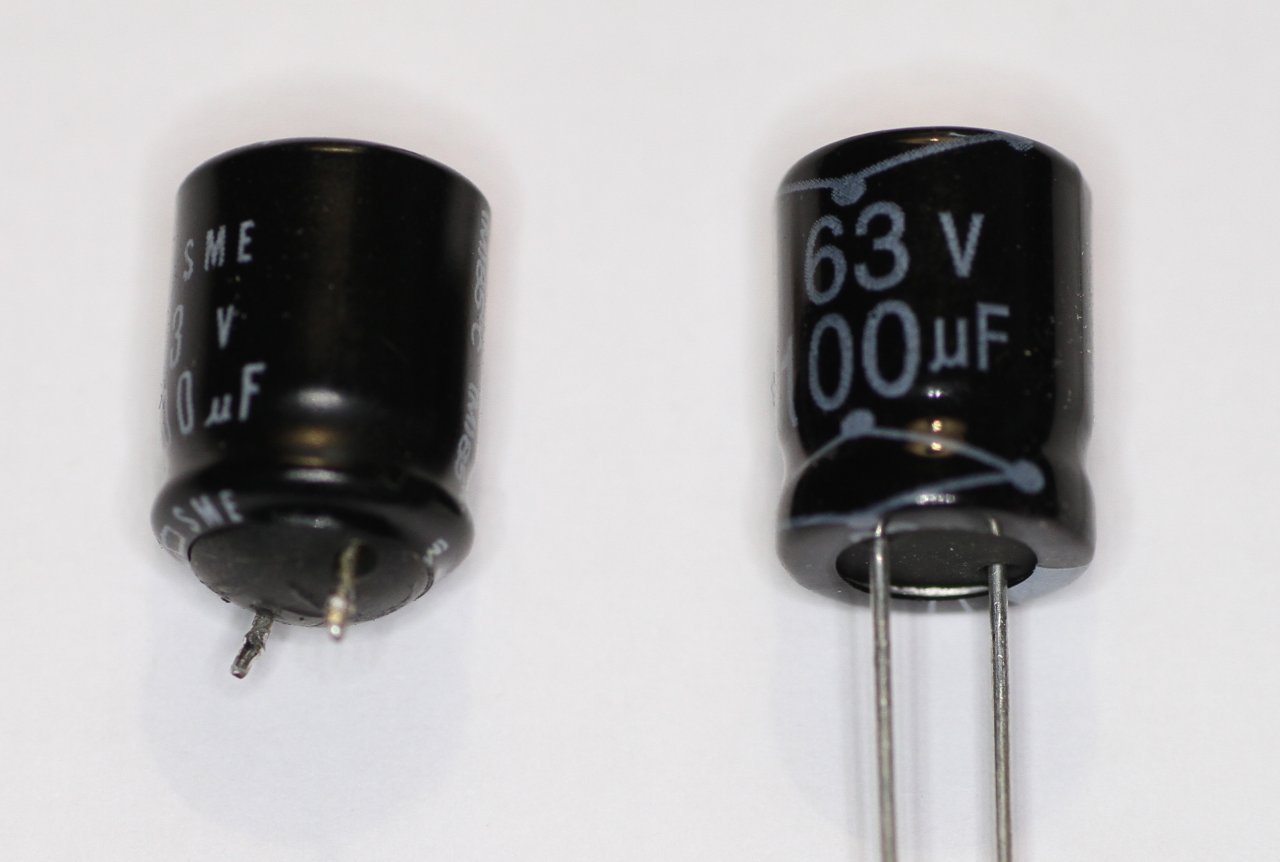
Two electrolytic capacitors: the one on the left is "inflated" compared to a new one on the right. No need to measure: an inflated capacitor must be replaced.
But some electrolytic capacitors can be bad and still look decent. The only way of finding the faulty ones is by measuring them. Just measuring the capacitance may help, but it's not enough. It's much better to measure the equivalent series resistance (ESR) and compare it with the one of a known good capacitor. The bad news is that you need an ESR meter (or an RLC bridge); the good news is that it works most of the times in the circuit without removing the capacitors (unless you have several in parallel).
For replacement, use only new capacitors. Choose a good brand and keep in mind that good capacitors are expensive, but fixing a SMPS is hard enough and completely justifies the extra cost. Electrolytic capacitors exist in two flavours: 85 °C and 105 °C. I always choose the higher temperature because they last longer.
Â
After replacing all the faulty parts, there is still a reasonable risk of blowing them again, especially if the fuse was initially blown. So, for the first test, I replace the fuse with a 100Â W or so light bulb (or I put the bulb in series with the mains line). About the same bulb power of the SMPS is a good starting point, but it's not critical at all. This limits the power in case the short isn't fixed yet, prevents more catastrophic failures, and don't make me nervous in replacing fuses again and again. Wearing safety glasses is also a very good idea.
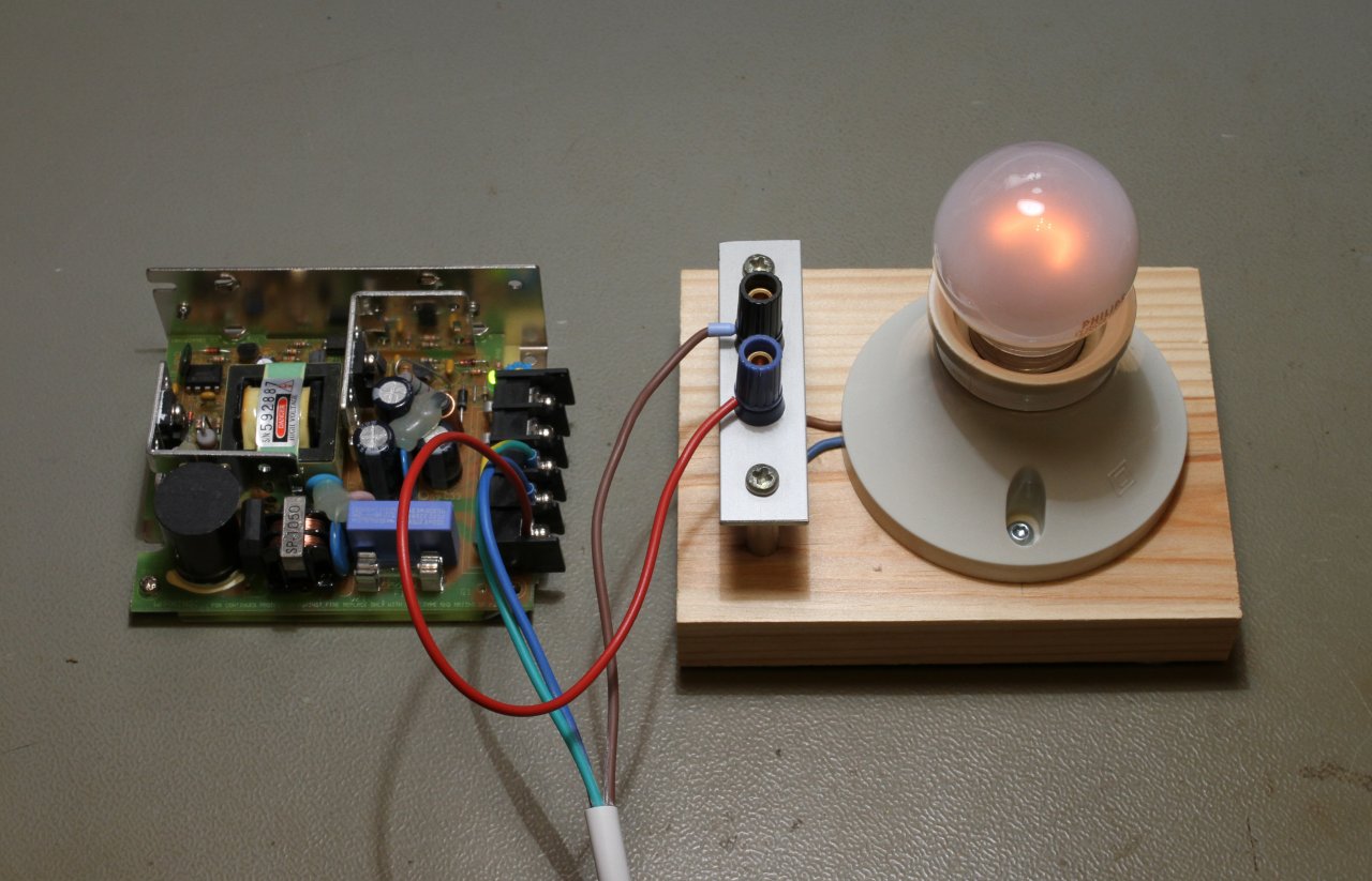
Put a light bulb in series with the AC mains line to prevent damage when first powering up a SMPS.
When you switch the power on (with no load) you'll see the bulb flash for a fraction of a second and than goes off (or glows slightly). If you still have a short circuit the bulb will glow bright and steady: just switch quickly the power off, discharge all the capacitors and start to look for the problem again.
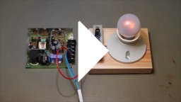
Watch a movie showing this trick on a healthy SMPS: lightbulb-trick-video.mp4 (3,215,292 bytes, 4 s, H264, 854 x 480, 24 fps).
In the above video, in order to make the light bulb glow with this low power SMPS, a 15Â W bulb has been used, since a 100Â W one wasn't glowing at all. The bulb is initially off; the flash is due to the inrush current when switching the SMPS on (charging of the high voltage filter capacitor), than the brightness goes down showing little current. Of course, if you load the output the bulb will glow brighter.
Several ideas for fixing SMPS have been explained, not with the intent of being an exhaustive troubleshooting manual, but more as a collection of tricks that you may find useful. I tried to summarize the way I usually proceed and share some of my experience; other people may very well have a different approach. Since SMPS can fail in a lot of different ways, you may still not find the right hint in this page, but I truly hope you'll find here useful information and that your SMPS will be back in business soon.
| Guiana - Guyenne |
| Niça i l'ordre de Malta |
| ConcĂ²rdia d'AlcanyĂs |
| Voltaire, TĂ cit i els Catalauni |
| La volta catalana a mĂªxic |
| CatalĂ i occitĂ , diferents en 13 punts |
| ProjecciĂ³ Da Vinci octant |
| Reflexions sobre el tĂtol del Lazarillo de Tormes |
| Liber elegantiarum |
| Esc - Esca - FĂ²mit - Fomes - FĂ³mite - Yesca |