// Global includes
#include <htc.h>
__CONFIG(FOSC_INTRCIO & WDTE_OFF & PWRTE_OFF & MCLRE_OFF & CP_OFF & CPD_OFF);
/*
*
*/
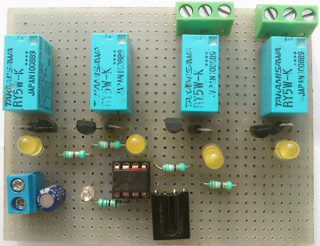
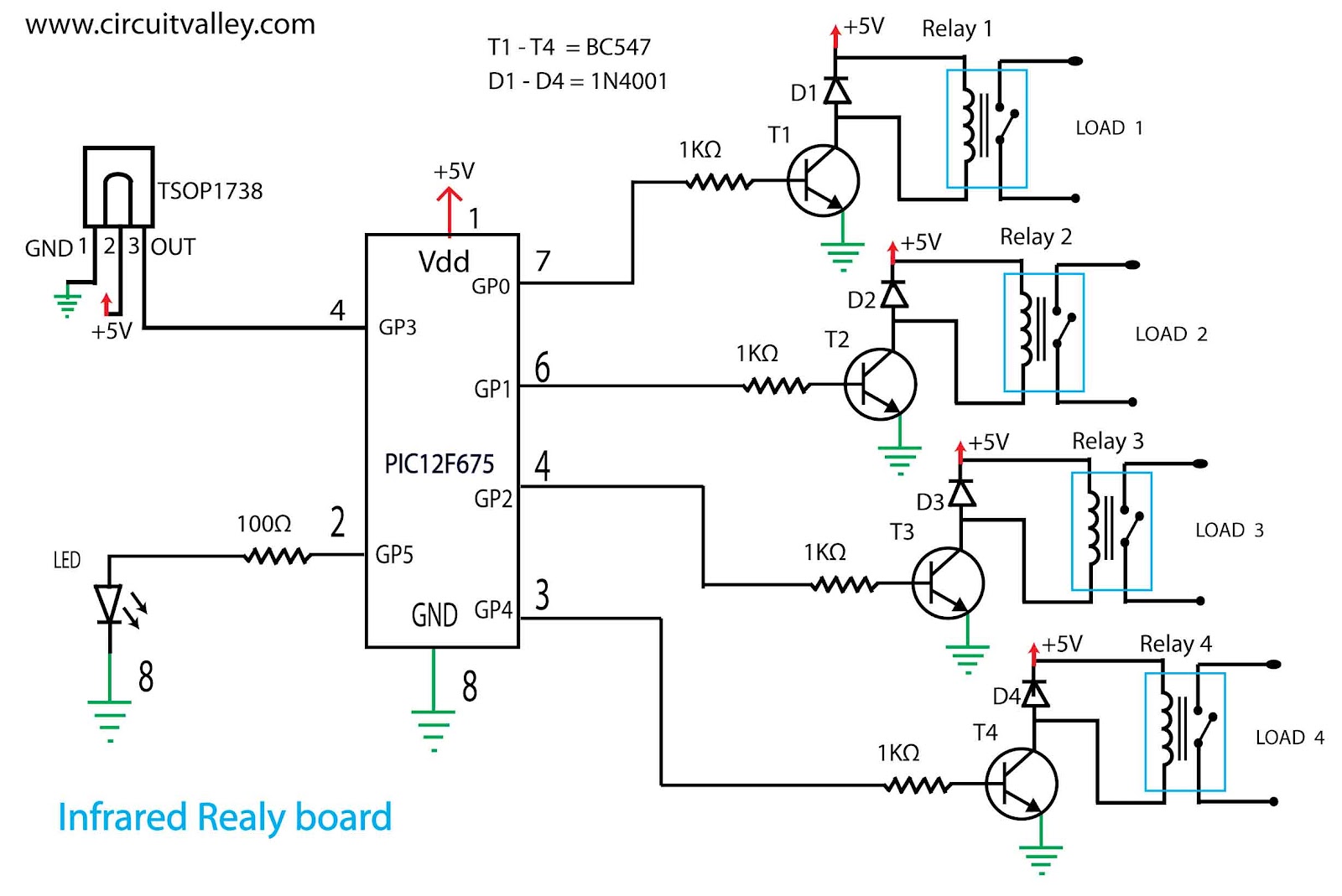
#define LED GPIObits.GPIO5 // IR port status indicator LED defination
#define RELAY1 GPIObits.GPIO0 // RELAYS PORT definations
#define RELAY2 GPIObits.GPIO1
#define RELAY3 GPIObits.GPIO2
#define RELAY4 GPIObits.GPIO4
#define IRSENSOR GPIObits.GPIO3 // IR PORT defination
//#define TICKSPERMS 1004 // tick in a milli second
#define TICKS11ms 11044 // ticks in 11ms
#define TICKS5o5ms 5522 // ticks in 5.5ms
#define TICKS2o3ms 2309 // ticks in 2.3ms
#define TICKS3ms 3012 // ticks in 3sm
#define TICKS0o2ms 200 // ticks in 0.2ms
#define TICKS8ms 8032 // Tick
unsigned int TIMEOUT = TICKS11ms; // the pulse should occur before this time excede Otherwise it is an error
unsigned int PREPULSE = TICKS8ms; // the interrupt should occur after this time Otherwise it is an error
static unsigned short long timer; // varible to keep track of long timeouts ( it can also be int if you want to save flash memory for some other purpose )
static unsigned char dataready; // varible to use as flag when data is completly received and ready it is 1 else 0
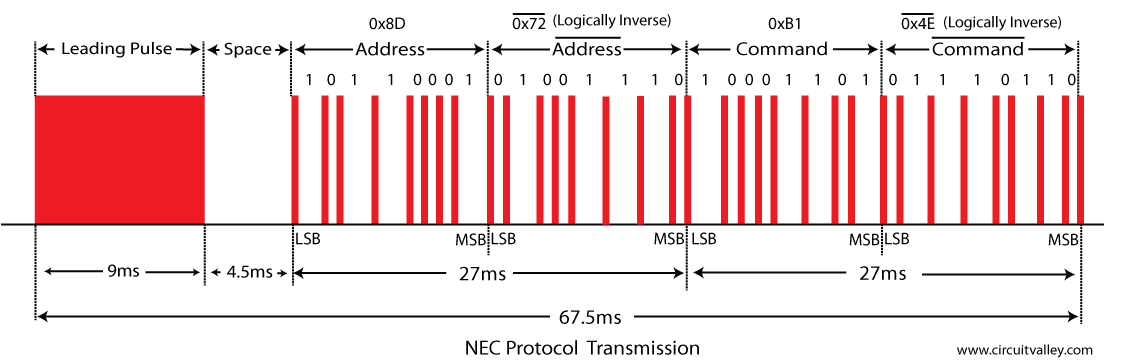
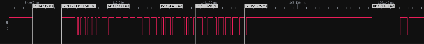
static unsigned char necpoj=0; /* (necpoj=NEC position )this varible is used to keep track of the edges of the input singal
as decoding of the singal is done by a state machine
so this varible acutalley sotores what state we currently are
and total bits 32 and 2 leading pulse */
static unsigned char address=0,notaddress=0; // these varible are used to store received address
static unsigned char command=0,notcommand=0; // these varible are used to store received address
void interruptOnChangeIsr(void); // interrupt service routine for interrupt on change of input port for IR sensor of mcu
void timerInterruptIsr(void); // interrupt service rouine for timer0
void interrupt t0intr(void)
{
if(INTCONbits.T0IF) // check the timer0 over flow interrupt flag
{
timerInterruptIsr(); // timer0 overflow interrupt has been occur call the isr
INTCONbits.T0IF =0; // clear the timer0 interrupt flag
}
else if (INTCONbits.GPIF) // check the interrupt on change flag
{
LED=1; // to blink the LED when IR signal is received
interruptOnChangeIsr(); // interrupt on change has been detected call the isr
INTCONbits.GPIF =0; // clear the interrupt on chage flag
LED=0; // to blink the LED when IR signal is received
}
}
/* THE main source code Start here*/
void main()
{
CMCON=0x7; // disable the comparator
ANSEL=0x00; // all pin are Digital
TRISIO=0x8; // Only GP2 is set to input rest are out
TMR0 = 0; // clar the timer
OPTION_REG = 0x88; //pullups are disabled
//timer0 clock source is internal
//timer0 perscaller is 1:1 (disabled "assigned to WDT")
IOC = 0x8; //interrupt on change is only to the GPIO3
INTCONbits.T0IE = 1; // Timer0 overflow interrupt enable
INTCONbits.T0IF = 0; // clar the timer0 intrrupt flags
INTCONbits.GPIE = 1; // external interrupt on GPIO3 pin(4) is enabled
INTCONbits.GPIF = 0; // clear the external interrrupt flag
INTCONbits.PEIE = 1; // peripheral intrrupt enable
INTCONbits.GIE = 1; // GLOBL interrupt enable
EEADR = 0x00; // load the state of port from EEPROM
EECON1bits.RD = 1; // Start reding EEPORM
GPIO = EEDATA; // LOAD The readed data form EEPORM to GPIO
while(1) // wait forever for the data received and ready
{
if(dataready) // data is received and ready to be procssed
{
// key1 0x50 to Toggle relay 1 // these are command of the IR remote control which i have
// key2 0xD8 to Toggle relay 2
// key3 0xF8 to Toggle relay 3
// key4 0x30 to Toggle relay 4
// key5 0xB0 to Turn off all the relays
switch(command) // swich on
{
case 0x50: RELAY1 = !RELAY1; //Toggle relay 1
break;
case 0xD8: RELAY2 = !RELAY2; //Toggle relay 2
break;
case 0xF8: RELAY3 = !RELAY3; //Toggle relay 3
break;
case 0x30: RELAY4 = !RELAY4; //Toggle relay 4
break;
case 0xB0: RELAY1 = 0; //Turn off all the relay
RELAY2 = 0;
RELAY3 = 0;
RELAY4 = 0;
break;
default :
break;
}
EEADR = 0x00; //Write PORT status to EEPROM
EEDATA = GPIO; // load the current status of GPIO to EEPROM write register
EECON1bits.WREN = 1; // Enable EEPROM write
INTCONbits.GIE = 0; //1 disable the interrupts as it may currupt the EEPROM data
EECON2 = 0x55; //2
EECON2 = 0xAA; //3 (1,2,3) require sequence
EECON1bits.WR = 1; // satart writing
INTCONbits.GIE = 1; // Enable the interrupts
dataready=0; // data has been processed so clear the dataready flag
}
}
}
void interruptOnChangeIsr(void)
{
unsigned short long tdiff;
unsigned char pin;
static unsigned long rxbuffer;
tdiff = ((timer<<8)+TMR0) ; // calculate how much time has been passed since last interrupt
// the time shold be less then time out and greater than PREPULSE
pin = IRSENSOR; // store the current status of Sensor
TMR0 = 0; // reset the timer0 to measure the next edge(interrupt) of input
timer = 0; // reset the timer varible to
/* state machine is started here and it totally managed and keeps track of its states using the varible necpoj
here are the details of necpoj ( NEC position ) varible
if
necpoj == 1 we just detected the first edge of the input singal it may also mean(if interrupt is not false) that the 9ms leading pulse started
after the first edge THE next pulse is expected to arrive around 9ms so the TIMEOUT is set to 11ms and PREPULSE is set to 8ms
necpoj == 2 we just detected the second edge of the input signal and we finished the 9ms leding pulse and now 4.5ms space started
after the second edge the next pulse is expected to arrive around 4.5ms so TIMEOUT is set to 5.5ms and PREPULSE is 3ms
necpoj == 3 we just detected the third edge of the input singal and we finished 4.5ms space and addres lsb is now started
after the third edge the next pulse is expected to arrive around 562.5us so TIMEOUT is set to 2.3ms and PREPULSE is 0.2ms (timeout can be much less at this state but to do this i have to add one more if else statemetnt)
necpoj == 4 we just decected the forth edge and the 562.5 us burt of LSB of address has ended now a little space for '0'562.5us or for '1' 1.6875ms
after the forth edge the next pulse is expected to arrive for '0' around 562.5us and for '1' 1.675ms so TIMEOUT is set to 2.3ms and PREPULSE is 0.2ms
necpoj ==5 to 66 data pulse keep comming
TIMOUT and PREPLUSE remain same as above.
necpoj ==67 we just fined the command inverse MSB space not the final 562.5us burst has stated so we fined the receiveing
now we will check the address and command for being correct
*/
if ((tdiff>PREPULSE) && (tdiff<TIMEOUT) ) // the edge (interrupt) occurrence time should be less then the TIMOUT and greater then PREPULESE else it is an fake singal
{ // At the very first edge (necpoj==0) this conditon will always false and the false block of this if will bring the state machine (necpoj) to position 1(position 1 means 9ms leading pulse has started now we have to wait for 4.5ms start pulse to occur)
if(necpoj==1 || necpoj==2) // when we are hear it means 9ms leding pulse has ended and now we are necpoj=1 or necpoj=2
{
if((pin==1) && (necpoj==1))
{
necpoj++;
TIMEOUT = TICKS5o5ms; // timeout for 3rd pulse 5.5ms
PREPULSE = TICKS3ms; // PREPULSE for 3rd pulse 3ms
}
else if((pin==0)&& (necpoj ==2))
{
necpoj++;
TIMEOUT = TICKS2o3ms; // now data starts so timeout is 2.3ms
PREPULSE = TICKS0o2ms;
}
else // this block handle the conditon if any error occur after the completing the pre pulses
{
necpoj = 0; //reset the state machine
TIMEOUT = TICKS11ms;
PREPULSE = TICKS8ms;
}
}
else if(necpoj>2) //now we are picking the data
{
necpoj++; //necpoj sill inrement on every edge
if(necpoj&0x01) // here we check the if necpoj is an odd number because when necpoj goes greater then 3 then
//necpoj will always be and odd value when a single bit tranmission is over
{
rxbuffer=rxbuffer<<1; //shift the buffer
if(tdiff>1250) //we are here means we just recevied the edge of finished tranmission of a bit
// so if last edge was more than 1.24 ms then the bit which is just over is one else it is zero
{
rxbuffer = rxbuffer | 0x1;
// GPIObits.GPIO5 = !GPIObits.GPIO5;
}
else
{
rxbuffer = rxbuffer |0x0;
// GPIObits.GPIO4 = !GPIObits.GPIO4;
}
}
if(necpoj >66) // we have reached (Leading pulse 2 +address 16+~address16+ command 16+ ~command 16+ last final burst first edge 1)=67th edge of the message frame means the date tranmission is now over
{
address = (rxbuffer>>24)& 0xFF; //extract the data from the buffer
notaddress = (rxbuffer>>16)& 0xFF;
command = (rxbuffer>>8) & 0xFF;
notcommand = (rxbuffer) & 0xFF;
rxbuffer=0; //clear the buffer
if((!(address & notaddress)) && (!(command & notcommand))) // check weather the received data is vaild or not
{
dataready =1;
}
else
{
dataready=0;
}
TIMEOUT = TICKS11ms; // weather we received the vaild data or not we have to reset the state machine
PREPULSE = TICKS8ms;
necpoj=0;
}
}
else
{
TIMEOUT = TICKS11ms; // some error occured reset state machine
PREPULSE = TICKS8ms;
}
}
else
{
if(pin==0) //we are here means that after a longtimeout or PREPULSE we just detect a pulse which may be the start of 9ms pulse
{
necpoj = 1; // yes it could be the start of 9ms pulse
}
else
{
necpoj = 0; // no it's not start of 9ms pulse
}
address = 0xFF;
notaddress = 0xFF;
command = 0xFF;
notcommand = 0xFF;
dataready = 0x000;
TIMEOUT = TICKS11ms; //default timing
PREPULSE = TICKS8ms;
}
}
void timerInterruptIsr(void)
{
if(timer<0xFFFF) // this code is to increment the variable timer's value on every over flow but this if conditon will prevent this variable form rollover when a long timeout occurs
timer++;
}