N5ESE's Classic RF Probe

(click on any picture to see larger version)
Â
NOTE: 'N5FC' is my former call.
This project was constructed while that call was valid, and you may observe references to it. |
The RF Probe is one of the handiest accessories you can have around the shack. Using only 3 electronic components, it may rank as one of the simplest and cheapest homebrew projects. The one featured here cost about $10 in parts and supplies, not counting the wire, which I scrounged. When used with a high-impedance DC Voltmeter, it can be used to measure RF voltage (and power), trace RF signals in a new design, and troubleshoot malfunctioning RF circuits. It has its limits, of course, and we'll discuss those here. But once you understand how it's used, and how easy it is to build, you'll wonder why you never built one before.
Â
What's an RF probe, and how does it work?
You might think of an RF probe as a special test lead that converts your regular ol' DC voltmeter to a RF reading voltmeter. Why not just read it using your trusty voltmeter, set on AC? Well, because most voltmeters wont read AC signals having a frequency above 10 or 100 KHz, and RF is way above that. [You can buy special RF-reading voltmeters, but they're very expensive... a homebrew RF probe is dirt-cheap]. Let's examine how an RF Probe works.
Â
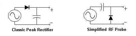
Above left, we see the schematic of a classic half-wave peak rectifier, commonly seen in power supplies. It's pupose is to take an AC signal at the input (usually from a transformer or the AC line), rectify it, and charge a capacitor. If you don't take a lot of power from the circuit (i.e., if your load doesn't draw a lot of current), the capacitor charges up to the peak voltage of the AC signal, and stays prettty much constant. Notice the simplicity of the circuit: not counting the load, we see it is an AC Source, a diode, and a capacitor in series.
Above right, we see a simplified schematic of the RF Probe. At first glance, it looks quite different from the circuit at the left. But notice: just like the first, it consists of an AC Source, a diode, and a capacitor in series. It's pupose is to take an AC signal at the input (usually from a circuit under test), rectify it, and charge a capacitor. And just like the first circuit, If you don't take a lot of power from the circuit (i.e., if your load doesn't draw a lot of current), the capacitor charges up to the peak voltage of the AC signal, and stays prettty much constant.
What's the difference between these two circuits, then? One small little thing, really. In the first circuit (the half-wave peak rectifier), any positive DC component gets added to the voltage at the output. In the second circuit (the RF Probe), the circuit is insensitive to positive DC components. This is good for an RF probe, because we're going to be testing circuits with DC biases applied, and we don't want those biases to affect our readings (we're interested in the AC only, i.e., the RF)
In both these circuits, if we place a DC (not AC) voltmeter at the place where it says "+" and "-" we'll read a DC voltage that is approximately equal to the peak of the applied AC voltage. If we knew our applied AC was a sinusoidal signal (or sine wave), then we could divide our reading by 1.414 to obtain the RMS value, which is the way we usually measure AC voltages. Even if it's not a sinusoid, at least we know what the peak voltage is, and that's something we didn't know before we started.
We'll do one more little trick to make the RF Probe more useful, and it will only cost us the addition of a 2-cent resistor. So that we don't have to manually divide our readings by 1.414, we'll use a resistor to create a voltage divider that will do it for us. Here's a classic voltage divider, added to our RF Probe circuit:
Â
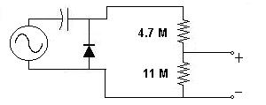
As we know from elemental electronic theory, the voltage across the second resistor (where it says "+" and "-") is equal to the applied voltage multiplied times the ratio of the second resistance divided by the total resistance in series. In our case, for a sinusoidal input, we know the applied DC voltage is equal to the PEAK of the AC voltage. We would like the resistor divider to divide by 1.414, which means that the total resistance in series (including the second resistor) needs to be equal to 1.414 times the second resistance. In our example circuit, shown above, the second resistor is 11 Megohms, and the total series resistance is 11 Megohms PLUS 4.7 megohms, or 15.7 Megohms. Is this ratio 1.414? Pretty close, about 1.427, closer than the typical resistor tolerances.
But wait! I said we would add one resistor, not two! What's up with that? Well, the 11 Megohms is the typical input resistance of a high-impedance voltmeter, like an electronic VTVM or a digital voltmeter. As long as it's 10-11 Megohms, it'll give results close enough for government work (HI). Obviously, it's important to know what your voltmeter's input resistance is, and you can find this out in your voltmeter's specifications, or measure it (I wont get into that). And really, accuracy is often not that important, especially when you're signal-tracing.
Â
Enough! Let's get real... let's build something!
Here's a complete schematic of the classic RF Probe. Simple, eh?
Â
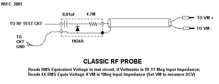
We've added a few things from our theoretical discussion that we'll make short note of. Obviously, for "probing" we need a "probe". (Hey! No wonder I get paid the big bucks...). We add a SHORT lead with an alligator clip. The alligator clip goes to our circuit "ground" and the probe goes to our test circuit, where we're probing. Brilliant! We don't want either of these to be long leads, because we're talking RF here, and long leads = antennas, and we don't want to be picking up stray signals or broadcasting them. 10-12 inches for our ground lead is sufficient for circuits to up to 30 MHz.
As shown in the schematic, we'll need to shield the RF Probe circuit, or else our hand and body will pick up stray RF and couple it into the circuit, causing erroneous readings. We'll also shield our leads all the way back to the Voltmeter, as shown, for the same reason. At the far end of the shielded wire, we'll mount banana plugs (or whatever will fit our DC Voltmeter).
In case you're tempted, don't make poor substitutions for the diode. We chose the 1N34A because it had the following key characteristics: Reverse Breakdown Voltage greater than 40 Volts, forward voltage (barrier potential) of less than 0.3 Volts, and good RF qualities. Any diode with these qualities (example, the 1N458A) would work as well, but the 1N34A is readily available (at Radio Shack and others). Silicon and Shottky (hot-carrier) diodes, while good RF devices, have higher barrier voltages, and will not work as well at low RF voltages. The 1N34A is a germanium device, and with a barrier voltage of around 0.25 V, provides about the best performance you can get with this simple circuit.
For best accuracy, size the resistor to match your DC Voltmeter's input impedance:
R = 4.7 Meg for Zin = 11-Meg;
R = 4.3 Meg for Zin = 10-Meg;
R = 430 K for Zin = 1-Meg;
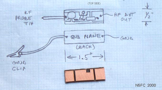
Here's one cheap-and-easy approach to building the RF Probe:
Â
 Click on the image above to see a larger
Take a small piece of scrap double-sided printed-circuit board, about 1-1/2 x 1/2 inches, Groove it on one side only, similiar to the image above, to create pads for soldering, but leave the back side as a "ground plane". Mount your diode, capacitor, and resistor as shown, soldering to the pads you made. One side of the diode (the non-banded isde) gets connected to the ground plane (drill a hole through to the other side and solder it). Try to fit all the components neatly inside the edges of the pc board. Solder the braid of the shielded wire (3-4 ft long) to the ground plane, and the center conductor to the pad with the resistor. Also, solder a 10-12 inch hook-up wire to the ground plane. Check that there are no shorts between the center conductor and the ground-plane. Solder the probe tip to the pad with the capacitor (I used a discarded probe tip from a broken test probe).
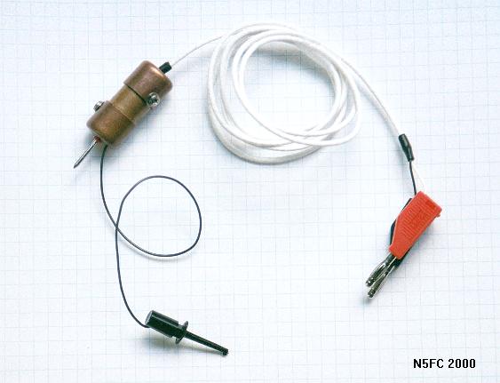
Here's where we get creative: packaging! One way or another, whatever method we use, it's important to shield the probe circuit, yet without shorting any part of the circuit to our shield (except the ground plane). I was on a kick of using copper pipe, which is very cheap, so I built my shield out of 1/2-inch copper pipe and end caps, commonly available at your local hardware store. I drilled a hole in the end of each end-cap, to pass the shielded cable and the probe tip. I used a shouldered washer to insulate the probe tip from the end cap, but a small rubber grommet would have worked as well. Stuff the assembly inside the copper pipe, and you end up with a completed probe that looks like the following:
Â
Click on the image above to see a larger version
Â
So, how do we use this thing?
Before we use it, a few precautions are in order. Don't use the probe in any circuit where the highest DC supply voltage is greater than the diode's reverse-breakdown voltage. For the 1N34A, this is 50 Volts. Same goes for the capacitor, which should be rated at least 50 Volts. This probably means that the probe cannot be used in most tube circuits. Also, don't try to measure RF power in circuits where the peak voltage will exceed 50 Volts. What will happen if you exceed these voltages by a little? Well, probably nothing; possibly, the diode or capacitor will fail open or short.
The first thing you'll always do in using the RF Probe is to connect the banana-plug end to the +/- jacks of your DC Voltmeter; set the Voltmeter to DC-Volts (not AC).
To use the RF Probe for signal tracing in a malfunctioning RF circuit or a homebrew circuit, connect the aligator clip to a convenient "ground" or "common" point in your circuit. Often this is the chassis. Most of the time, you'll be probing at the base/gate, emitter/source, or collector/drain of a transistor, one either side of a coupling capacitor or transformer, or at the input or output of an IC. Because the circuit's RF must overcome the diode's barrier potential (of 0.25V, for our 1N34A), voltages much less than that won't read at all, and voltages less than about a volt won't read very accurately. Typically, RF and post-mixer-amps in receivers don't have enough RF voltage, unless you inject a very strong signal at the input.
I recently used my RF probe to troubleshoot my dead TenTec Scout, which had suddenly quit transmitting in mid-QSO. I connected the rig to a dummy load, then keyed it while probing. Using the probe, I was able to follow a steadily increasing RF signal through the transmit chain, from the oscillator through the transmit mixer, to the pre-driver, and the driver. The actual voltage measurements weren't important, just that they were increasing from stage to stage where expected. Then, (whoops!) the driver's base circuit had 6 Volts, but the collector circuit only had only 0.1 Volts! The driver transistors had gone south!
You can also use the RF probe to measure RF power with reasonable accuracy, up to about 50 watts in a 50-ohm circuit. By 50-ohm circuit, I mean a 50-ohm antenna system at 1:1 SWR (higher SWRs are not 50 ohms), or a 50-ohm dummy load. Assuming the resistor in your RF probe is sized to match your DC Voltmeter's input impedance (as explained above), you will get quite reasonably accurate measurements using the following formula:
Â
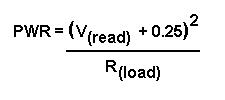
For example, I want to measure the power out of my TenTec 1340 40-Meter QRP transceiver. I place it on a 50-ohm dummy load, and key down. I generally use a BNC-Tee adapter to gain access to the output line, but I could as easily pop the cover off. Using the RF probe (alligator clip to chassis ground), I measure12.2 Volts (DC) (and the same RF RMS Volts). Plugging this into the formula above I have PWR= (12.2 + 0.25) * (12.2 + 0.25) / 50 = 3.1 Watts. The rated power for this rig is 3 Watts, so I've verified everything is hunky-dorey.
We've added the potential barrier to the measured voltage above, but that little trick doesn't work so well when you get down around a volt, and for voltages less than about a volt, the measurement accuracy suffers greatly. Also, the diode's response is severely non-linear below the barrier potential, and will generally read much less than expected in circuits where the RF voltage is less than 1/4 volt. So if you see tiny readings in circuits where it's normal to have voltages less than 1/4 volt RF, don't get too spun-up about the low readings... it may mean everything is normal. My rule of thumb for guessing at this is as follows: For collector/drain circuits in oscillators or transmit-chain amplifiers in key-down, expect RF Voltages about 20-50% of the applied DC (supply) voltage. This depends on the circuitry, of course, but it's a reasonable gesstimate. Base/gate and emitter/source circuits will generally be much less, maybe 5-10%. Circuit impedance will affect this too.
Â
How good is this thing?
Well, we're not talking high performance test equipment here, but we are talking very useful. If you account for the barrier voltage, the readings can be quite accurate when measuring most low-impedance circuits (20-200 ohms), provided that the voltage is above 1 or 2 volts. How accurate? +/-10% from 200 KHz to 150 MHz would be a reasonable expectation. Also, the voltage divider is only accurate for sinusoidal signals. If you want "peak" measurements, simply multiply your reading by 1.414. The "peak" measurement should be good regardless of whether the waveform is sinusoidal. Regarding ultimate accuracy, your results may vary, and you may want to compare it to a laboratory instrument at the frequency of interest if you're really interested in accuracy. If you shield it well, and keep the ground clip lead reasonably short, it should be good in low-impedance circuits up into the VHF region, and down into the upper-audio region. In higher-impedance circuits, the junction capacitance of the diode may cause a low-pass effect at higher frequencies, and you're most likely to see this as a loss of measurement accuracy (i.e., low readings) at frequencies above 30 MHz. This doesn't mean it's not useful; it just means it reads low. Also, the capacitance of the probe may affect some sensitive RF circuits. For example, if you're probing a LC-tuned oscillator circuit, it may stop oscillating or change frequency or become unstable. Actually, most any probe will do this. Also, as we said before, the barrier voltage becomes a bigger part of the measurement error as the circuit voltage drops below a volt or so, and becomes dominant as you approach the barrier voltage. Just keep this in mind as one of it's limits.
Enjoy, good luck, and 73!
monty N5ESE
____________________________________________________________________________________________________________
How KI6DS Built the N5ESE RF Probe
Paul Maciel, AK1P and I decided to create some interest and fun in the NorCal meetings, and perhaps give the guys a reason to show other than just to visit. We decided to do a "Kit of the Month" with the rule being that the selling price of the kit could not be over $5. We just want to recover cost of the parts and provide some seed money for the next month's kit.
Our first kit was the Pipsqueak Regen Receiver, designed by Paul Harden, NA5N, and published in QRPp several years ago. That was a popular kit, and the idea was well received, so we decided to continue it this month with an RF Probe designed by Monty Northrup, N5ESE. Monty has all of the details on how to build the probe on his website at http://www.io.com/~n5fc/rfprobe2.htm If you decide to build one of these probes, be sure and visit Monty's site for all the info.
I gathered all of the parts during the holidays and bagged them into kits. Originally we were going to sell them for $3 each, but Paul suggested that we give them away to the brave members who showed up at the meeting today even though the swap was rained out. So, we did.

Parts Kit for N5ESE Ball Point Pen RF Probe
The parts needed are shown above. From left to right, top to bottom they are: 5" x ÂĽ" piece of double sided pcboard, 2 banana plugs, 1/8" shrink wrap, ÂĽ" shrink wrap, 24 inches of RG174 (or other suitable shielded cable), 3" dissecting pin, 1N34A Germanium Diode, 4.7 Meg resistor, .01uF capacitor, alligator clip, #24 insulated stranded hookup wire, 1 Bic Round Stic Pen.
Ok, now it is time to start building. The first step is to cut through the top layer of copper, being careful to just go through the copper. You want to make 3 separate pads to solder to. I used a small hacksaw to do mine, but you may wish to use a dremel, fret saw, etc.

The pcboard after it has been cut into 3 "islands"
Next, take a nibbling tool, or a file, and cut a slot out for the germanium diode. Use the diode as a gauge.

The pc board with the slot cut out for the diode.
Next take the straight pin, and with a pair of strong pliers, cut off the head. Be care to shield your eyes. Next, solder the pin to one end of the pcboard, on the same side as the slots.

Close up of straight pin after it has been soldered onto pcboard. (The red is flux)
The next step is to solder the .01 capacitor to the pcboard as shown.

The board with the capacitor soldered in place.
Now we will solder the resistor in place.

The resistor is in place.
Now find the Germanium Diode. Be very careful with it, as it is somewhat fragile. Do not make a sharp bend in the leads near the body, or you will break the diode. Note that one end has a band on it. Place it as shown so that it solders to the same side of the pc board as the capacitor and resistor.

The banded end of the diode is soldered in place.
Now, flip the pc board over and solder the other lead of the diode to the ground plane side of the double sided pc board.

The other end of the diode is soldered to the ground plane side of the board.
We are just about finished. It is starting to look like a probe!! Next, prepare the ink pen body. Take the pen apart by pulling on the ink tip. When you get it out of the pen body, pull off the ink tube. Next take something to push out the pen tip, leaving just the plastic body. You will need to hold the pin tip under a faucet to rince out the ink left over. You will need to drill a 1/16" hole in the side of the pen to accommodate the ground wire and a hole just large enough to pass the RG174 cable in the end. I used a 1/8" bit for this.

The pen tip and tube after separation.
The next step is to solder the banana plugs on the RG174. Carefully peel the insulation back about 3", and unwind the shield around the center conductor. Place a piece of shrink tubing over the shield, and then connect each wire to a banana plug. Now take the other end of the RG174, and remove ½" of insulation and separate the center conductor and the shield. Solder the center conductor on the same side as the resistor, and the shield to the ground plane side as shown.

Center conductor soldered to resistor side of pc board.

Braid soldered to ground plane side of pcboard.
Next, take about 10" of insulated wire and connect it to the ground side of the pcboard by the probe tip. This will be threaded through the hole in the side of the barrel of the pen and then hooked to the alligator clip.

The ground lead for the alligator clip soldered on the ground side of the pcboard.

The completed probe.
Monty suggests that you use shrink wrap to cover your probe, then use either copper tape or the shield from RG-58 cable to shield the inside of the probe. Details are on his web page. One word of caution. This probe is only to be used in transistor circuits, NOT tube circuits!!
Enjoy.
72,
Doug, KI6DS
____________________________________________________________________________________________________________
I wanted to attempt development of a test procedure for alignment of a Bitx20 ssb transceiver using the most basic tools. I already had video's Videos of the process using an oscilloscope, signal generator and a spectrum analyzer. What was needed was a procedure using a RF Probe. I didn't have one so after a search of the internet, I found N5ESE's RF Probe His site has a very good explanation of how a RF probe works. This looked like just what I needed. After a search for a easily obtainable probe housing, I selected this.

The lowly "Sharpie" It can be found almost anywhere and many of us have old, dried up ones laying around. The first step was to remove the felt tip. This is easily done using a pair of needlenose pliers and giving it a pull. Then using an exacto knife, cut off the other end and remove the taperaed part.

Using the needle nose pliers remove the ink reservoir.

You now have a "custom" probe housing.

Next search through the junk box for all of the parts. I used a .02ufd cap because it was the perfect physical size, a 4.7 meg resistor, and a 1N34A diode. I had a nice, flexible, piece of test equipment wire for the ground. I found a copper nail that would be easy to solder to for a tip.

I soldered it all together as per the schematic being careful that nothing could short together when pushed into the probe housing. Using a little shrink tubing can help insure that it will work when assembled.

Next, carefully insert the soldered circuit into the housing, use a little hot melt glue to make the tip rigid and also in the back to strain releif the cables, add a alligator clip for the ground and banana jacks for the meter connection, test, and use.

Main Menu
Originally Posted by WC5P