
La vaca cega desconfiada
_FRASE_TOP
|
The know-how of mechanical watchmaking *
|
||
_Mechanical_clock_dating_from_1500.jpg?uselang=fr) Mechanism of a building clock dated 1500, modified with a pendulum brought back after the year 1670. |
||
| Domain | Know-how | |
|---|---|---|
| Inventory location | France | |
| *ô Official description Ministry of Culture (France) | ||
| modify |
||
A clockworkô mechanism is theô fundamental organ orô element of a watchmaking instrument (clock, pendulum, watch, etc.). Its main function is to "tell theô time".
Thisô mechanism is the result of aô mechanical assembly of parts, some of which may have a movement in relation to the others. Referred to as the primary mechanism, it then includes other more elementary mechanisms, of lower levels, such as the driving element, the gear train, the escapement, etc.
It is the progress of the various watchmaking mechanisms that has enabled the evolution of watchmaking science. This practice has been included in theô inventory of intangible cultural heritage in France since 2018.
The first trueô fully mechanical clocks date from the end of theô thirteenth century. From that time on, the first of theN 1 of the clock is to "tell the time":
To achieve this service function, "telling the time", the basic structure of the clock will remain more or less the same for centuries.
A brief technical analysis of the instrument makes it possible to visualize its layout and to determine the reference vocabulary usedN 2.
 Analysis of the mechanism of aô fifteenth-century foliot clock: Technical organizational chart.
The building blocks of the mechanism that correspond to a technical function include:
The main elements will be discussed in the order in which they are presented, following their evolution succinctly.
The first clocks were weighted. Known sinceô antiquity, this type of motor was used in the Middle Ages in theô mechanisms for striking water clocks. It is mainly composed of a weight attached to a rope wound on aô drum linked to the cog.
The function of this engine is to storeô potential energy when the weight is wound up and then to release it during its descent in the form ofô kinetic energy: the engine torque created will then transmit its driving force to the gear train.
It is originally made of stone, an economical material that can be worked easily. Its density is around 2,500 kg/m3. Used for several centuries, especially in building clocks, it was replaced, in miniaturized clocks such as wall clocks, weight clocks, comtoises, by weights made of cast iron, steel, lead, sometimes silver, whose densities were much higher (3 to 4 times more) and therefore took up less space.

Very old stone weights.

Weight: one made of stone, the other of cast iron.

Movement Stone Weights; Cast iron bell weights.
.JPG?uselang=fr)
Iron Parquet Clock Weight.
Originally a simple rope connecting the weight to the drum, it was replaced in theô 19thcentury by a steel cable. In miniaturized clocks, cords, gut cords and chains will be more suitable1.
 Drum and rope.
The cylinder is characterized by its diameter and length.
 Counterweight Alarm Clock, Yellow: Hours; Red: ringtone.
Diameter and length are directly related to the winding frequency. For example, if you have a 30 cm diameter drumô that makes one turn per hour with a 3 cm diameter rope, and you want to rewind only once every 24 hours, the length of the drum should be more than 72ô cm and the length of the rope should be 25 meters. This constraint of rope length partly explains the high location of building clocks and the full-time service of a "clock governor" responsible for winding and maintenance.
To gain length on the line stroke, it was of course possible to increase the frequency of winding or "to use a pulley that reduced the trajectory of the weight by half, but [sometimes] required the presence of a second weight"1 ; The engine weight must then be doubled to achieve the same effect.
In the twentieth century, the winding of the weight wasô automated. This is the case, for example, with theô astronomical clock in Bourges, which was automated in 19943.
In the miniaturized clocks of the modern era, such as theô Comtoises, the driving weights of the movement and the striking are sometimes linked to the gears by grooved pulleys and not by drums. The system then imposes a counterweight to keep the cord in the groove of the pulley.
The winding of the weights, whatever the solution envisaged to drive the gear train, requires a small mechanism - often aô ratchet - which allows the movement of the motor organ in one direction only, the direction of winding. The manual winding effort is transmitted to the system either via a capstan linked to the drum in the first clocks or by a crank. For the lightest weights, in the Comtoises for example, a key may suffice; In the pulley system, the winding action will be carried out by acting on the counterweight.
Hand-wound.
Self-winding.
Even before theô fifteenth century, theô mainspring appeared, which allowed the miniaturization of the clock.
This spring is wound inside a case, the barrel. When it is released, it will indirectly transmit the driving force to the geartrain.
This "flat spiral" type spring was originally made of hardened, tempered and blued steel, and later became made of high-strength treated steel of the cobalt (Co), chromium (Cr) or nickel (Ni) alloy type. It is calculated for a minimum winding frequency of 24 hours4,5.
In its first uses, the motive force generated is not constant, it decreases irregularly as the disarming progresses6. To overcome this drawback, a "fusûˋe" attached to the barrel will be used.

Insulated, "relaxed" mainspring.

Clock mainspring used without barrel.

Motor spring in its barrel.

Interior view of the mechanism.

Exterior view of the engine barrel.

Barrel in a mechanism.

Former barrel and fusee mechanism.

Mechanism in situation.

Barrel-fusee link by chain.

Full rocket mechanism.
Another mechanism used before the appearance of the rocket by German watchmakers is the stackfreed10, which slows down the movement of the spring. Its disadvantage was its consumption of motive energy when braking11.
 Stackfreed
Cogs areô gear trains that transmit motor torque and movement from the motor component to other elements of the mechanism12.
Aô gear consists of a wheel and pinion mounted on different axes; If a sprocket and a wheel are mounted on the same axis, it can be calledô mobile.

A classic gear with spur teeth.

A train of two gears.

The first is mobile: wheel and pinion side by side.

A second mobile: wheels and arbral sprockets.
Gears have been known since ancient times. The famousô Antikythera machine dated toô the year 87 B.C. bears witness to this; Gears with triangular teeth were already integrated into this complex mechanism, which even included a differential gear13.
In watchmaking, the teeth of the wheels can be of different types; On the gears of building clocks, the profile went from a triangular shape to other more elaborate ones, determined by trial and error, then, in theô seventeenth andô eighteenth centuries, to more scientific profiles: the epicyclic profile and the involute profile of the circle allowing transmission by bearings, therefore without slipping and theoretically without friction14.
 Epicyclic tooth profile.
Each gear train element is made from specific materials:
The wheel is the element with the largest diameter. Originally made of iron, then steel, these metals have often been replaced byô brass or, better,ô bronze, alloys that are less oxidizable and have less friction.
This is the designation of the small diameter wheel in a gear. It spins faster than the wheel. Because of this, it tends to wear out faster. The sprockets were therefore made, most often, of iron and then of treated steel to compensate for this wear. There is an exception to the use of the above-mentioned materials: the wooden gears of clocks made in theô Black Forest and sometimes inô Spain.
 A gear with a spindle pinion, also known as a lantern gear.
In watchmaking, meshing ratios are important: for example, between the hour and seconds display there is a ratio to be obtained of 1/3600. This involves the construction of sprockets with as few teeth as possible (for sprocket teeth, the profession also says wings).
The shafts, known as "shafts" for shafts with a large diameter in relation to their length, receive the sprocket. The materials used throughout the ages have changed from iron to treated steels for obvious reasons of resistance. Their cylindrical or pivot-shaped ends16 are supported by bearings or bearings integrated into the cage structure.
The first clocks, with a simple mechanism, had only an "hour cog".
At the ends of this cog were:
In more modern clocks and watches, the basic cog is the "minute cog"; It transmits the movement to the timer17, a secondary gear train placed under the dial, which communicates the rotation of the minute pinion to the hour hand.

Minute gear train (in yellow) and minute track (in purple) for the hours.

Simulation in the movement.

Another configuration, perspective view.
In a single gear train, theô gear ratio18 is equal to the product of the number of teeth of the driving wheels divided by the number of driven wheels.
ô

With:
 and ÿ¢§ÿ¢§
 respectively the angular velocities at the input and output of the gear train;
 , the product of the number of teeth of the driving wheels;
 Detail of the minute track of the Huygens clock.
 , the product of the number of teeth of the driven wheels.
ô
In the minute track of the Huygens clock, taken up by Bion (see above), which communicates the rotation of the minute pinion to the hour hand, we have:
The gear ratio is (30 x 6) / (30 x 72) or 1/12 which corresponds well to the fact that The hour hand makes one turn of the dial while the minute hand makes twelve.
Other gears may be involved in the movement, particularly in watchmaking instruments with complications: clocks, pendulums, watches where indications other than hours, minutes and seconds are displayed, such as the date, the diurnal movement of the Sun, the phases of the Moon, the zodiac, etc.
 Schûˋma d'ûˋpoque de rouage de complication pour le mouvement du Soleil, ca. 1446.
Le rouage de sonnerie, autre rouage particulier, sera intûˋgrûˋ, plus loin, dans le mûˋcanisme de sonnerie.
Leô mouvement d'un mûˋcanisme d'horlogerie simple comme une horloge û poids, comporte trois ûˋlûˋmentsô : le moteur, le rouage et le rûˋgulateur19,1.
Sans rûˋgulateur, la descente du poids moteur est unô mouvement rectiligne uniformûˋment accûˋlûˋrûˋ. Il sera transmis au rouage sous forme deô mouvement circulaire uniformûˋment accûˋlûˋrûˋ, mouvement ne convenant pas û l'indication rûˋguliû´re des heures.
La fonction ô¨ô rûˋgulateurô ô£ va rendre le mouvement du rouage pûˋriodique et assez rûˋgulier pour ûˆtre considûˋrûˋ, û l'éil commeô circulaire uniforme. Ce sera l'invention qui correspondra û la naissance de l'horloge mûˋcanique û l'aube duô xive siû´cle.
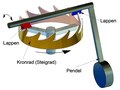
The regularization of the movement is obtained from two intimately related elements: theô escapement and theô oscillator20,21 that have evolved together.
 Foliot regulator: R + V escapement ( (emerald green), F oscillator (meadow green).
It is the first recognized regulator, first described in 138522 and used for more than six centuries. It is composed of three elements:
The accuracy of this type of controller, according to the authors, was in the range of half an hour to an hour per day24,25. However, this variability has never been found by measurement N 6.
The escape mechanism can be considered, for the purposes of study, as consisting of:
"There are as many escapements as there are famous watchmakers!" exclaimedô Jean-Andrûˋ Lepaute in 1755. Louisô Moinet's engine, invented in 1816 and still functional and preserved today inô Saint-Blaise (NE), beat at 216,000 vibrations per hour, makingô Louis Moinet the inventor of High Frequency in terms of escapement.
Today, there are more than 2,500 of them, which can be grouped into families. These include: the rod escapement, described above, which will adapt to different types of oscillators, the lever escapement, the cylinder escapement, the lever escapement, the pin escapement, etc.26,27,28.
To yard.

Anchored.

Cylinder.

Lever-operated.

Ankle-studded.

Ankle-studded.
There are only three types ofô oscillators orô regulating organs: theô foliot, the pendulum, and theô pendulum.

Galileo's Pendulum Clock Project, 1659 drawing.
Huygens' first pendulum clock, known as a pirouette clock, 1658.

Huygens' second clock, with cycloidal pendulum, 1673.

Seconds clock, described in detail, 1709.

Pendulum suitable for a lever escapement.
There are about ten varieties31.

First pendulum? also known as crown foliot, Dondi, 1364.

Balance, simple steering wheel, with a rod escapement.

Balance-spring.

Balance-spring, scale, 1753.

Bimetallic or compensating balance.

Compensating balance wheel in situation.
As its name suggests, it "encloses the entire mechanism of the different types of watchmaking instruments".
On the first clocks, whether indoor or building, its structure, generally parallelepiped in shape, is made up of an assembly of iron bars connected by corners, a kind of sloping keys. Later, these corners were replaced by dowels and bolts, but this type of skeleton lasted until theô nineteenth century for building clocks. Later, at the same time, the cage was transformed into a cast iron frame for the so-called horizontal bell towers.

Wrought iron assembly wedge, ca. 1500.

Iron cage, with pegs, 1546.
.jpg?uselang=fr)
Here, bolted and keyed elements,ô eighteenth century.

Cast iron horizontal clock frame, 1910.

Another cast iron building,ô twentieth century.
Brass will advantageously replace iron in miniaturized clocks, whether indoor or traveling. The structure of the latter will result from an assembly ofô plates connected by pillars32 ; Square, hexagonal in shape, it will also be adapted to the circular conformation of watches.

Iron lantern clock, ca. 1500.

Plates A and B and pillar Z in the Huygens clock, 1673.

Marine clock, mostly brass, 1763.

Watch with brass plates and pillars,ô 16th century.
One of the functions of the cage is to support the axes of the mobiles at their ends.
Originally, they were simple holes drilled in the plates or pillars, sometimes square in shape, in steeple clocks. Inserts, bearings or bearings33, will improve the axis guidance function. More precise, suitable for lubrication, especially by oilers34, they will be interchangeable. Initially made of steel or bronze, they were replaced in certain places on the watches by "stones"35 ", as early as theô eighteenth century. These will be natural stones (garnet, agate, diamond) or synthetic stones (corundum, rubies), materials that reduce friction and thus reduce the wear of the surfaces in contact36.

Some brass or bronze pads.

Cylindrical pivot andô stone-type bearing.

The so-called "conical" pivot and its stone counter-pivot.
Dial andô hands are indicators. They make it possible to fulfil the main function of a watchmaking instrument: "to tell the time".
They are often presented together in a descriptive and artistic setting regarding a style of clock or watch. Here, only the historical aspect of these two elements will be developed.
The first clocks were blind, i.e. they had neither a dial nor a hand; they just ring. This audible information, which occurs only once an hour, at the "chime hour", will soon be supplemented by a continuous display, first by placing a fixed index in front of the graduated hour wheel, then thanks to the dial and hand pair. The dial, attached to or in front of the cage, hasô 24 time divisions and the hand is unique. This hand, attached to the end of the hour gear, does not have a fixed direction of rotation, it can rotate clockwise or retrograde. All of this took place before theô 1400s37.
![Roue des 24 heures de l'Astrarium de Dondi[Lequelô ?] : il est 22 heures û l'index (1348-1364).](https://commons.wikimedia.org/wiki/File:Astrarium_Dondi_roue_des_heures.jpg?uselang=fr)


24-hour clockwise clock in St. Mark's Square inô Venice (late15th century).
The evolution of clockô faces was first reflected in a display on two times twelve o'clock, thus limiting the number of strikes, then in a twelve-hour turn of the dial, and evenô six o'clock in Italy.

Dial 2 x 12 o'clock clock ofô Chartres Cathedral (1528).
.jpg?uselang=fr)
12-hour dial of theô Gros-Horloge deô Rouen (dial 1527).

6 o'clock dial ofô the Quirinal Palace inô Rome.
In addition to indicating the time, the dial and hand combination will be able to provide other information corresponding to the various complications of the clock (the course of the Sun, the Moon, etc.). This multiple display was the result ofô astronomical clocks from theô fifteenth century.
Theô hour hand saw the appearance of its little sister, theô minute hand, before the end of theô sixteenth century, on an auxiliary dialN 7. After changing size, it joined the hour hand in the centre of the dial at the end of theô 17th century, made by the English watchmakerô Daniel Quare in 1686N 8. It is interesting to note here that on the circumference of the dial, "the 'hour' interval is [theoretically] divided into four for one-hand clocks, and into five for two-hand clocks38.ô ô£

Clocks by Tycho Brahe with auxiliary dials, 1598.

Hevelius' two- or three-hand clocks, 1673.
At the end of theô 16th century,ô Tycho Brahe owned clocks that indicated the second of time. One of them had a wheel of 1200 teeth and a diameter of two cubits (about 80ô cm))39but he was not much pleased with their accuracy; later, the seconds hand will appear, probably because of the application of the pendulum by Huygens around 1660-1673 and the needs of astronomy: in the years 1670-1680, in France, astronomers such as Jeanô Picard,ô Jean Richer,ô Dominique Cassini use pendulum clocks whose accuracy is given for a fewô seconds of time per 24 hours. It was first read with a pendulum in 1671, then on a secondary dial before 170940 and, finally, the second hand reached the centre of the dial in 173041.

Seconds wall clock by Bion, 1709.

Lepaute's parquet clock, ca. 1770.
MûÑllinger's central second hand clock.
From this time on, another hand will be able to indicate theô dates.
The display considered here isô analog. In the second half of theô twentieth century, another type of indicator was introduced, the digital display, where the hands disappeared from the dial, which then only served as a frame.
The first clocks were "chiming" exclusively. They indicated a particular time, such as the time of rising in religious communities. A few decades later, the innovation was to strike every hour with a number of strokes corresponding to the time given by the time mechanism. Advances, linked to the needs of users, brought complications to the basic ringing.
The following mechanisms can therefore be distinguished:
 Alarm clock ringing mechanism.
Whatever the chime intended, it is the hour gear train that triggers the striking gear train.
This is the simplest and oldest type of ringtone. Unfortunately, sources are practically non-existent before theô sixteenth century N 9.
The striking mechanism (shown in yellow in the figure) is grafted onto the clock cage so that the clock's hour gear can trigger the mechanism. The latter has an engine weight and a rod escapement that will act on a striking hammer.
The exhaust system is not balanced, the engine weight is determined by trial and error so that the movement is not too accelerated.
Ifô n pinions are placed on the so-called hour wheel, the engine can be triggered several times, provided that the engine weight is raised.
This alarm clock mechanism is borrowed fromô Diderot and d'Alembert's Encyclopûˋdie, 176342.

Front view of the alarm clock with its highlighted adjustment dial.

Striking mechanism only highlighted.

Simulation of the mechanism.
Summary Comments:
It is linked to the invention of shot counting. The first clock to strike the hours was the Milan clock, dated 133644 ; There does not appear to be any technical documentation for it. One of the earliest surviving examples of this type of mechanism can be seen on the clock ofô Salisbury Cathedral, dated 1386 (see below).
It is controlled by a wheel with notches, the spacing of which regulates the number of strokes struck.
As with the alarm mechanism, the chiming of the hours is grafted onto the clock cage, in parallel with the movement, so that the clock's "hour" gear train can trigger the mechanism via the roadway45 acting on a trigger lever. This striking mechanism is composed of the same elements as the movement mechanism, i.e. a motor, a gear train and a regulator:
 Ringing cog.ô ;
ô

Simplified diagram of a mechanism.

Example of a mechanism.
![Exemple sur l'horloge de la cathûˋdrale de Salisbury[N 10] (1386).](https://commons.wikimedia.org/wiki/File:Salisbury_Cathedral_2012_11_new1.jpg?uselang=fr)
Example on the clock ofô Salisbury CathedralN 10 (1386).
This type of chime can "count" (ring out of tune, i.e. without matching the display) when the hands are operated51. The counting wheel was used until the 1720s. Later, the chaperone appeared, having the same form and function, but with a different design (attachment to the barrel shaft)52.
 1820 drawing of a clock built in Paris in 1379 by Henry de Wick.
It is a bell in which the number of blows struck is regulated either by the position of a rake whose teeth operate the lifting of the hammer. On theô Comtûˋ clocks, the rake is replaced by a rack. These two types of ringtones do not count.
_6_fr.png?uselang=fr) Partial rake ring mechanism.
Partial rake ring mechanism.
The rake chime is triggered in the same way as the counting wheel chime: the pavement linked to the minute wheel will act every hour via a pin on the trigger leverô bc. The latter will, among other things, raise the esse53 d attached to the small triggerô a which will release the stop wheel; The striking mechanism then kicks in.
 Snail.
The striking of the hours is obtained from a cam, called a snail54, centred and oriented towards the hour wheel. The twelve o'clock to strike corresponds to the twelve sectors of this cam, in relation to the position of the hour hand; Thus the striking mechanism controlled by the hour hand does not count. On this cam, the probeô g will allow the rake to be lowered when it is released by erasing the esse simultaneously with the release of the stop wheel: in position I on the snail, the rake descends by one tooth, in position III it descends by three teeth... up to twelve teeth in position XII. The descent of X teeth will allowô you to hitô X shots atô X time.
This is the rake or comma lift55 s on the stopping wheel which will raise the rake of a tooth at each turn and which will control the strike with a blow of the hammer (mechanism not shown). When the rake is fully raised, the leverô bc having been lowered, the esse tilts, stops the rake in the initial high position, and the leverô a locks the stopping wheel by its pinô h.
On the Comtoises, the rake is replaced by a rack; One particular site describes the striking mechanism in its entirety with its illustrations56.
"This chime comes to us from England, it was adapted to watches by Messrs. Edouard Barlow and Daniel Quare. In France, it was Honorûˋ PONS who filed a patent for the "rake ringing for the clocks of Paris" in 1829.57.
They relate to particular indicators or sophisticated ringtones.
ô
![]() : Document used as a source for this article.
: Document used as a source for this article.
| Princeps namque |
| Castells catalans |
| ELS NOU BARONS DE LA FAMA |
| 1640: Festa del Pilar al 12 d'octubre per a descatalanitzar el descobriment i la Chiesa de Santa Maria in Monserrato |
| The age of Charles V |
| De Navigazzione - Cotrugli - Barca |
| Buscar tres pies al gato |
| Trobat a Irlanda el derelicte de la nau Juliana |
| Barca llevantina |
| Escola hispaniola de Viena |

Afegeix-hi un comentari: