
La vaca cega desconfiada
_FRASE_TOP
| 04-02-2014 (3429 ) | Categoria: RemotePark |
200 meters remote control with safety cover, four push buttons
This 200 meters four button remote control module the most widely used in the security alarm with antivirus solutions, garage door remote control, motorcycle or automobile anti-theft alarm and other fields, such uses require the remote control of the remote control is not far away from the general 50 meters is enough, but the requirements: low-priced remote control modules, transmitters handle small, delicate appearance, the provincial power consumption as much as possible, work stable and reliable.
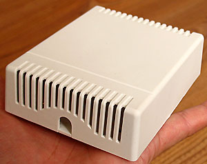
Here are the size of the transmitter is very compact in size only 58x38x8 mm, the use of high-quality plastic shell, with insurance cover, to prevent the misuse of touch buttons, antenna, when pulled out 13 centimeters long, remote control, only 20 grams.
Products 1:200 m peachwood color 315M four key remote control with key ring 10, a technical standard: 315MHz operating frequency and 2262 encoding chip resistors 1.5M (including a battery-A23)
Products peachwood 2:200 m 433M-color four key remote control with key ring 10, a technical standard: 433MHZ frequency and 2262 encoding chip resistors 1.5M (including a battery-A23)
Dimensions: 58x38.5x13 mm transmitter power: 20 mW operating current: 14 milliamperes operating voltage: 12V A23 battery alarm exclusive operating frequency: 315MHZ
Technical standards: PT2262/1.5M oscillation resistor compatible data bit keys: A: 10 B: 11 C: 12 D: 13
This is 200 meters four button remote control of the internal structure, we have adopted PT2264 chip (and as PT2262), marked on the board for the oscillation resistor R9, we have adopted a 1.5M resistor oscillation batteries are the top 1 ~ 8-bit address code switch region, Customers can use the method of short-circuit solder address code settings.
|
Coding fired resistor chip oscillation
|
Matching receiver decoder chip resistor oscillation
|
|
|
PT2262
|
SC2260-R4
|
PT2272/SC2272
|
|
1.2M
|
200K
|
|
|
1.5M
|
5.1m
|
270K
|
|
2.2M
|
390K
|
|
|
3.3M
|
12M
|
680K
|
|
4.7M
|
20M
|
820K
|
Products 3:200 m C double bonds, paragraph peachwood color key chain remote control with 10 yuan a technical standard: 315MHz operating frequency and 2262 encoding chip resistors 1.5M (including a battery-A23)
The photo shows transmitter shape, panel has on A, B, C, D 4 and a launch control button indicator. Internal transmitter using SAW resonator frequency stabilization, frequency, consistency is very good, very high stability, operating frequency 315MHz frequency stability better than 10-5, no need to adjust the frequency in use, especially suitable for many hair close one radio remote control system, etc. use some of the market on low-cost radio-controlled module is still using LC oscillator, stability and consistency of poor, even with high-quality fine-tuning capacitor, when the temperature changes or shock after they have been very difficult to guarantee good frequency debugging offset will not happen, resulting in shortening the distance fired.
This is equivalent circuit transmitter
This is the internal structure of the remote control, we used in 2262 are soft packaging chips, can reduce the volume of lower costs, the words marked RC oscillation are 1.5M patch resistance, can be 200 ~ 270K and the receiving end the use of oscillation resistor matching.
Receiver module:
Receiver module from the work hours can be divided into superheterodyne receiver board and receive???board. Receiver has a circuit???easy, moderate performance, low-cost advantages in practical applications so widely used.
This is???receiver equivalent circuit:
Receiver module using SMD SMT production process, which includes orthopedic amplification and decoding circuitry, the product technical characteristics:
1. Antenna has selected frequency input circuit, rather than relying on 1 / 4 wavelength antenna frequency-selective role in controlling the distance can be short or even close to removing an external antenna.
2. Receiver circuit self-radiation of small, together with the circuit module back mesh grounding the role of copper foil shielding can reduce the self-oscillation signal leakage and the intrusion of outside interference.
3. Receiver with high-precision inductor copper skeleton to adjust to the frequency of??after the 315M, which is adjusted using adjustable capacitor circuit receiving the frequency compared to temperature, humidity mechanical stability and anti-vibration performance have greatly improved. Adjustable precision capacitance adjust lower, only 3 / 4 laps of the adjustment range, and adjustable multi-turn inductor can adjust. Adjustable capacitor can not adjust after??, because regardless of conductor or insulator, various media around or invasive capacity will cause the capacitance changes, thereby affecting the receiving frequency. In addition, without the adjustable capacitance??by vibration and dynamic boards boards displacement between; temperature changes will????boards and dynamic changes in the distance between film; humidity changes due to changes in changes in media capacity; long-term Working in wet environments but also due to boards and dynamic changes in the capacity of oxide films, which will seriously affect the stability of the receiving frequency, and using adjustable inductance can solve these problems, because the inductor can be carried out after the adjust??, insulator??agent inductance will not change, but also because of the use of SMD technology, so even if the strong do not have to worry about receiving vibration frequency drift, the receiving circuit to receive bandwidth is about 500KHz, the factory has been adjust the center frequency at 315MHz, receiver chip inductance on the fine-tuning some of the adjustable frequency range of 5MHz, the use of not easily change, so as not to affect performance.
???latch receiver board of $ A-L4 10 a
Size: 48x20x8 mm oscillation resistor 270K. And coding can be compatible with 2262 chips, resistors for oscillation frequency to work from 1.5M to 315M supporting the use of remote control.
???receiver 7-pin modules named: 10,11,12,13, GND, VT, VCC, (VCC : 5 ~ 6V power supply terminal, GND terminal for grounding, VT pin with decoded effective output, as long as a button is pressed in the remote control device of, VT can synchronize the output high, release the button as soon as low, 10,11,12,13 decoder chip are PT2272 (SC2272) four output data latches , have signal when the output of the high around 5V, drive current of about 2mA, and the transmitter on-one correspondence of the four buttons here are used to latch L4 chip so latch data can be output.
As antenna can be used a length of 23 centimeters of wire directly soldered to the antenna hole, in general a longer antenna can improve receiver sensitivity, the figure refers to the red arrows oscillation resistor, here are the 270K, can be 1.2 ~ 1.5M oscillation resistor supporting the use of transmitters.
Non-latch type???rectangular receiver board A-M4 10 of $ 1
Size: 48x20x8 mm oscillation resistor 270K. And coding can be compatible with 2262 chips, resistors for oscillation frequency of job 1.5M of 315M supporting the use of remote control.
Receiver Board A-M4 and A-L4 is the difference between right and wrong data output latch, and has remote control signals are the data pin is high, remote control signal disappeared when the data for the immediate resumption of low-level foot.
Ultra-small type???rectangular latch receiving board of $ AX-L4 9 a
???ultra-small non-latch-type rectangular receiver board of $ AX-M4 9 a
This is also the receiver decoder with???board, but the volume is very small, only the use of 36x17x8 mm patch of the SC2272 chip oscillation resistor 270K, the back of the pin modules have functional tagging. And coding can be compatible with 2262 chips, resistors for oscillation frequency to work from 1.5M to 315M, supporting the use of remote control.
Superheterodyne Series
Superheterodyne receiver higher prices, temperature adaptability, job stability and reliability, anti-interference ability, product consistency, and receiver sensitivity of-101dB. Receiver local oscillator radiation low, no secondary radiation easily through the FCC or CE standards, such as testing, in line with industry norms, fit relatively poor business environment in all weathers.
Receiver Board B-L4-315MHZ latch needle inserted superheterodyne receiver board (16 a) size: 41x24x6 mm
Receiver Board B-M4-315MHZ needle inserted non-superheterodyne receiver latch plate (16 a) size: 41x24x6 mm
Receiver Board B-L4-433MHZ latch needle inserted superheterodyne receiver board (16 a) size: 41x24x6 mm
Receiver Board B-M4-433MHZ needle inserted non-superheterodyne receiver latch plate (16 a) size: 41x24x6 mm
Size: 48x20x8 mm to receive the frequency of oscillation resistor 270K and 315M can 1.5M resistance oscillation of 315M supporting the use of 2262 remote control, 433M receiver SMD LED board instructed otherwise receive state also leads to a slightly different pin, please refer to physical tagging shall prevail.
Superheterodyne receiver plate on the left side of the red arrow is the antenna terminal can be used as an antenna wire 23 centimeters. Here are the superheterodyne receiver board using high-performance wireless remote control and digital ASIC RX3310A, if the operating frequency of 315MHz using 316.8MHZ of the SAW resonator; if the operating frequency of 435MHz using a 433MHZ SAW resonators. Superheterodyne receiver module has an inherent disadvantage, that is too remote control signals will interfere with the local oscillation signal causing obstruction to the normal received signal, then open as long as a certain distance such as 10 meters will be able to work properly.
We work in order to test whether the normal receiver module can be at the receiving module VCC and GND terminal plus a 5-volt DC voltage, respectively, at 10,11,12,13,17 client to take a light-emitting diodes (LED anode grounding) to latch receiver plate as an example: When we pressed the A button when the transmitter, instead of the corresponding 11 Road to light-emitting LED, the A button transmitter release, 11 of the LED is still lit road in a self-sustaining state ( latches), until the other keys pressed key such as B, 11 and 12 extinguished the LED light. 17 side are effectively decode the output, regardless of which transmitter pressed a button, that is, as long as the decoder into a high success, transmitter to stop firing immediately extinguished.
Multi-purpose single-1J-L4 remote control relay board to receive 2 4 yuan a volume: 70x50x20 mm
(Frequency 315MHZ / oscillation resistor 270K / can work in the latch or non-latch mode matching shell 3.8 yuan a 12V power supply supporting 10 yuan a)
The remote control receiver board, and the website can introduce the 100 meters four button remote control, 200 meters four button remote control, 800 meters four button remote control, 2000 meters four button remote control, such as 500 meters with the use of the emergency button. Uses: used for remote control of a circuit OFF, or a bright light and out.
The blue arrow on the board to receive the location of the PCB through the solder Department can select four-way short-circuit to switch the remote control signal in one of the way (such as remote control key A / B / C / D of the A button) to another also can be red arrows with solder short / open circuit to switch select latch or non-latch mode. The default is open non-latch mode, that is, press the A button, receive board relay pull-in, release the A key if the receiving plate to release the relay. If post-solder circuit latch mode, that is, press the A button, the relay board to receive the merger to maintain suction, only press the B / C / D in any of a button, the relay before being released.
Have practical experience of users will find that, under the same conditions, using M4-chip non-latch plate to receive the remote control distance is much smaller than the L4 latch-type remote distance, and sometimes only half of latch-type or even less than and relays have the phenomenon of pull-in instability, This is because in the non-latched state, the remote control signal required about 30 times per second, synchronization, when the relay controlled by the electrical load, or are prone to interference with other equipment, equipment itself after the electricity generated would interfere with the remote control signal interruption, so that the relay at a job jumping instability.
Here we use a wide anti-jamming technology exhibition pulse method is still used for L4 decoder chip output by 17 feet the signal to do a delay of about 0.5 seconds wide outreach, so that the output signal of the remote control more stable, the development of the remote control station at the gate products that adopt this approach, so that the remote control further, more stable and Practice has proved that lagging 0.5 seconds delay will not affect the operation.
Four multi-purpose relays 4J-L4 remote control receiver board 30 yuan a size: 71x84x20 mm
(Frequency 315MHZ / oscillation resistor 270K / can work in the latch or non-latch mode matching shell 3.8 yuan a 12V power supply supporting 10 yuan a)
The receiver board can be 200 meters and four button remote control, 800 meters four button remote control, 2000 meters, such as four keys with the use of remote control.
The receiver of the four relays on the board corresponding to the four button transmitter, blue arrow Department can use solder to short-circuit and open circuit switch select latch or non-latch mode. The default is open non-latch mode, that is, press the A button, receive board relay pull-in, release the A key if the receiving plate to release the relay. If post-solder circuit latch mode, that is, press the A button, receive board relays A suction to keep the merger, only press the B / C / D of a button any time, A before the release of the relay, press the That way the relay pull-in, that is to receive remote control board can be the last memory state, and be able to maintain a self-locking until the next time the remote control to receive commands to change the status of the relay.
Each relay has a corresponding red light-emitting diodes to indicate the status of its work, the upper left corner of the circuit board are 12-volt power outlet DC power input, each relay has a corresponding three terminal, are One group of normally open to normally closed contact, between the public side, the left always right for the normally closed, you can control about 220V/5A load, if the long-term control of a larger proposal to increase the load current relay 220V / 20A expansive flows to extend relay life.
The receiver board has also been adopted by non-latch mode pulse broadening anti-jamming technology, so the stability of the remote control, remote control distance and have a lot of customers to buy long-term supporting their products, because the long-term large-scale use will inevitably lead to some failures, here we introduce the way 4J-L4 about the repair techniques.
First of all, you can measure whether or not to receive the first two ends has 5V voltage? , There is no power on the part of the focus of inspection, the general 78L05 are damaged or PCB disconnected (disconnected in general and the PCB pad happened at the junction, it is difficult to detect concealed the naked eye, can be used to confirm multimeter) to receive the first because it is a separate small plate so easy because the transport caused by squeezing or shaking the roots of tear caused by poor contact pad, plus careful observation confirmed multimeter.
Measuring the output of the first receiving terminal voltage, the normal remote control signal receiving board does not generally fluctuate at around 2V, when holding down the remote control when the voltage down to 1V or so, release the remote control hopping transient voltage to 3V, then return to around 2V fluctuations. Can be disconnected if we do not receive the first of 14 to 2272 feet measured between the jumper and then click, or not receiving the first note damaged Change (my website has sales of 315M to receive???first 7 yuan a) Please check if the return to normal 2272 L4 chip.
2272 L4 measurements of the 5V power supply normal? Address whether the dirt area code or address inconsistencies and remote control? Press the remote control 17 feet when it has synchronized voltage output? If there is no damage may be 2272, if the 10 ~ 13 can synchronize the output signal, please Detect whether the overall transistor 8050 non-performing (PCB have latched on to write the word next to the transistor), can short-circuit CE pin board can look at the receiver can latch at job state? If we can explain failures in the total capacitance of the transistor and the 100UF and 4148 diode and 100 ohm resistors here, please check whether it has???
If you are a certain way does not work, please relay this road Detect SC8050 and the LED is bad? Please focus on whether the line PCB inspection, and finally can doubt whether the bad relays can test voltage test. Judging by the fault Occurrence: receiving the first bad-2272L4 damage-PCB disconnected -8050 damage-78L05 damage-LED damage - bad relay.
Receiver Board 4: AC power supply multi-function double relay receiver strip shell 24 yuan a technical criteria: be in line with the job oscillation frequency 315MHZ PT2262 chip resistor of 1.5 ~ 4.7M remote control and remote control the use of metal 1527
This is our latest multi-function double relay improved receiver board, which communicate directly with 220V power supply, and with a plastic shell, it can simultaneously control two-way load AB, but also through the jumper cap to different handoff data channels, such as the 200 meters with four button remote control can be flexibly set different remote channel button corresponding to AB. And its operating mode selection switch can be flexible, you can work at point move, two types of trigger flip mode, as long as the board will receive the VT and adjacent - with solder short circuit (under the map the location of the red arrow) will be able to move into a type, default is triggered when the left turn so in transition.
We use this product at the time required and the remote control code click on the study, methods is relatively simple: will receive the plate L and N terminal connected to 220V AC, the study by the lower right corner of the white button (required Note: At this point the entire receiver board with a 220V AC voltage, and capacitor step-down circuit is non-isolated circuit, should not have the Do not touch any metal on the device, so as to avoid electric shock!)
Hold down the button at 3 seconds later, heard the buzzer and then release the call button, press the remote control has been studying the button, then buzz will be able to express an immediate halt to the success of study at this time will be able to synchronize remote control, We can study more than 2262 encoding chip operating frequency is 315M, the oscillation of the different resistance 1.5M address of the remote control code can also study U.S. Products 4:100 m 1527 Luxury metal remote control.
If you need the address of the previous study all the delete key, you can always hold down the Learn button, buzzer, etc. Do not call after the release, and then beep sound, etc. to stop studying when pressed by the remote control button, then buzz calls 5 sound, that have been deleted!
The Product of the relay output mode defaults to the line of fire control, you can switch through the solder (see right) as an independent relay type, the so-called FireWire output type is the direct control of the firing line output, for example, this time at zero line L and A Firewire output ACF after another on 220V light bulbs, then A timely relay suction bulb will light up, A relays release bulb goes out, and very suitable for direct control of the use of 220V load occasions. And independent-type relay is the relay contacts and 220V complete isolation, only the equivalent of a normally open contact. When A relays absorptivity A always timely and A public conduction closure, when A relays release A normally open and A public open disconnect.
Receiver Board 5: DC power supply Multifunction board four relays to receive 27 yuan a shell with the technical standards: be in line with the operating frequency 315MHz oscillation resistor 1.5 ~ 4.7M of 2262 or the remote control 100 meters luxury metal remote control using 1527
DC power supply Multifunction board and four relay receiver communicate a single power supply relay and double relay the biggest difference is 12V DC power supply must be used, and its mode of use of jumper caps to switch more convenient, as long as the red arrow the location of the jumper cap to wear to the L position for the latch, M to be a dynamic model, each mode must be re-up after the electricity to be effective.

Products using the four groups 10,11,12,13 independent output relays, each road relay contacts are normally open to normally closed contact output, Central is a public contact, the above contacts are normally open, the following are normally closed contacts can be very convenient to control the light bulbs, energy-saving lamps, fluorescent lamps, motors and other types of load, and other performance parameters can refer to a single multifunction relay.
315/433MHZ the DF wireless data transmission module
100-meter four-channel remote control circuit
200 meters four channel coding remote control circuit
500 meters non-shell four-channel remote control circuit
500 meters 12-channel coding launch remote control receiver module circuit
500 meters one-touch wireless alarm emergency button
800 meters four channel coding remote control circuit
2000 meters the ultra long-range four-channel coding remote control circuit
This page of the remote sales Product shipped eight address code are vacant, so different models can co-remote control, but the 8-bit address code when vacant job may be affected by the environment the impact of interference signals will appear maloperation, so customer recommendations reference here to information on its own change of address after the purchase code, attention: the launch and receiver must be synchronized in order to address the remote control! Remote control by the physical distance between the actual environmental impact is generally a nominal distance of 10 ~ 50%.
|
Dual in-line 2 yuan per board 2262
|
20-pin wide-body 2262 patch 2.5 yuan per board
|
|
2272 M4 dual in-line 2 yuan per board
|
Ultra-small SMD SC2260-R4 per board 2.5 yuan
|
|
2272 M6 dual in-line 2.5 yuan per board
|
2272 L4 DIP 2 yuan per board
|
|
2272 L6 dual in-line 2.5 yuan per board
|
20-pin wide-body 2272 M6 patch 2.5 yuan per board
|
|
2262 IR dual in-line 2 yuan per board
|
20-pin wide-body 2272 L4 patch 2.5 yuan per board
|
|
2272 T4 dual in-line 2.5 yuan per board
|
20-pin wide-body 2262 IR patch 2.5 yuan per board
|
SC Series are compatible with PT series, 100PCS Price over another you
RX3310 an integrated circuit chip 6 yuan
315 SAW 2 yuan a component 316.8M SAW 2.5 yuan a component (with the RX3310)
433 SAW components 2 yuan a 435M SAW 2.5 yuan a component (with the RX3310)
Search PT2262/2272 chip set introduction and coding details please click
All Products Price Bank account number and order Know orders flow orders immediately!
PHS: 0513-83082087 Tel / Fax: 0513-83342087 Contact: Xie Gang
Office Address: Zip code 226200, Jiangsu Province, Qidong City No. 511 Middle Road Jianghai Crystal Court A1
E-mail: ![]()
Laboratory of Electronics Production www.xie-gang.com website just qidong Electronics Co., Ltd. brief introduction into