A year ago, on July 19th, reader Jeff posted that he had an inexpensive Chinese motion detectors that used the 2262 chipset. He was having some trouble getting it working with the r06a receiver as in my July 2012 post â HERE. It seems that I must look at 2262/2272 every July?
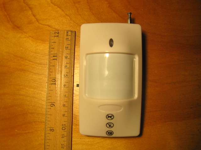
Anyway, almost a year ago I purchased a cheap Chinese PIR motion detector similar to Jeffâs. (See Figure 1 below). The purchase was just a whim to satisfy my curiosity about this type of PIR sensor. Jeffâs, however, was the now more common 9-Volt version. The one that I purchased operates on two 1.5V AA batteries. Of course mine is in 433MHz to match my existing r06a receiver.
I have uploaded a short video on YouTube where you can see a very short clip of the motion detector transmitting the event that is then received and displayed by my Arduino r06a test setup. Watch the video at https://youtu.be/LAcCXUpj6_Q
My 3V version is still for sale on eBay but you have to look for them. Use âWireless Pet Immune Infra Red PIR Motion Detectorâ in eBay search and theyâll pop up. The 9V version typically sells for significantly less than the 3V version â ~$4 versus ~$13. The listed specifications also show a shorter battery live for the 9V version than for the 3V version â 6-months versus 1-year. So take your pick â long battery life or lower cost.
As is usually the case with unbranded, inexpensive Chinese electronics, documentation is minimal, critical critical circuit board legends are missing and there are indications of imperfect work. Than said, as is also usually the case with unbranded, inexpensive Chinese electronics, it works!
I was rather flummoxed by the simplest electrical issue â battery polarity. The Chinese wired the battery compartment such that the positive lead was colored BLACK and the negative was colored RED. This is in violation of all accepted norms and practices and I was concerned that I would fry the circuit if connected that way. I poked around a little bit trying to verify correct polarity but eventually chanced plugged the batteries into their pockets and flicked on the power switch. Success â the single startup LED flash occurred followed, after a minute by three blinks indicated motion was detected. This device has a one to two minute delay before it is active. By the way, the external power switch is rather incongruous â I can imagine scenarios where it could be disarmed without motion detection, depending, of course, upon where the sensor was located within a room. Even more incongruous is an internal tamper switch that is defeated by simply turning off the external power switch. Truly odd! For what it is worth, tripping the tamper switch cause an event message transmission identical to a standard motion detection.
The single sheet of instructions contained enough Chinese-style English to identify settings options. Unfortunately, the both the printed diagram and the circuit board legends were in several cases completely missing. Some experimentation was required to completely identify the correct settings. Figure 2, below, shows my settings. I set the address to match my existing r06a test setup with an address of FFLHHHLF (A0 is rightmost digit). The four data bits are used to identify the sensor â I chose bit D1 low for mine (binary 1101).
I have been doing all of my tests with the antenna collapsed to its shortest length of which, including its internal portion is 80mm plus a circuit board portion of an additional 65mm. This yields an antenna length of 145mm which is little short of the optimal 433MHz Âź wavelength antenna of 173mm. However, since the antenna, including the circuit board portion, is not straight, is partially folded back upon itself and is in close proximity of metallic objects, 173mm wouldnât correct anyway. If the antenna were fully extended it would be a 390mm antenna â about a half wavelength. In any case, it works fairly well.
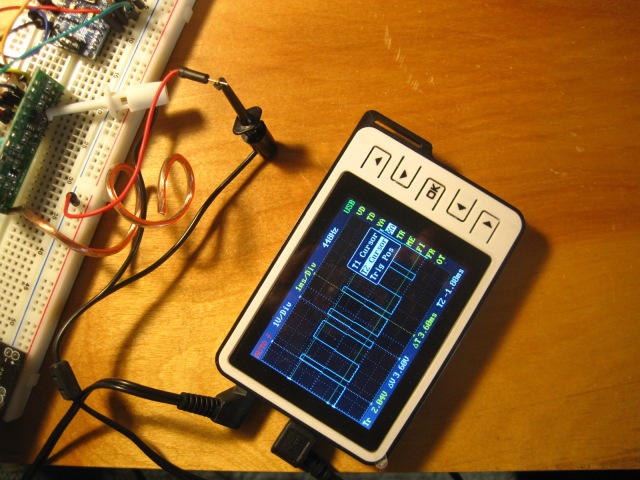
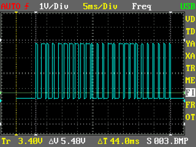
Now, Iâll delve back into the 2262/2272 protocol a bit. For protocol analysis I have connected my little DSO Nano v2Â Digital Storage pocket size Oscilloscope to the r06a receiver. I used the fob to transmit the observed data. Figure 3, below, is of the DSO Nano in use. In this particular measurement I am measuring the duration of a complete digit (two pulse train) â 3.6ms. Figure 4, below, is a close-up.
The DSO Nanoâs little screen cannot display the entire captured data sequence in a usable way but by adjusting the time/division displayed and sliding the screen back and forth, measurements are accomplished with the little screen.
The image below shows what an entire data sequence looks like on the DSO Nano V2:.
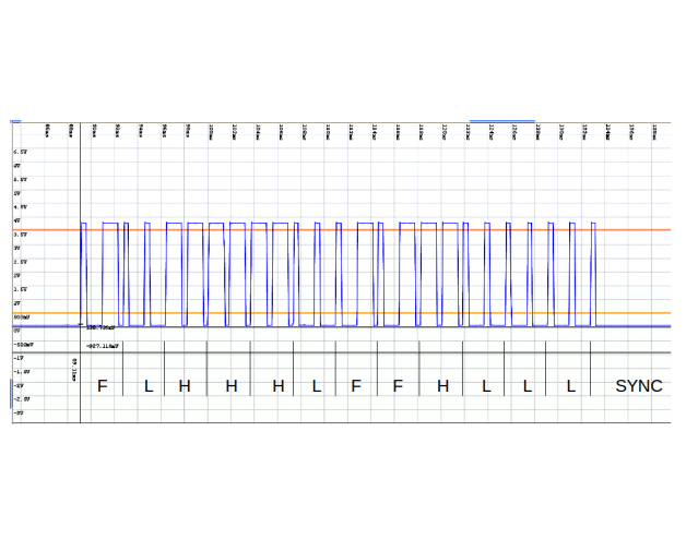
However, the DSO Nano IS capable of saving the entire capture buffer as an XML file. Converting the saved XML to an image is a bit of a challenge. Fortunately, there is a Windows .NET program named âbenfwavesâ than can make the conversion. MONO failed to run it and while the .net source for Microsoft Visual Studio 2010 Professional is available, I didnât want to take the time to see if it was possible to successfully build it using Microsoftâs  Free Visual Studio. Since I exclusively use Linux, I used Windows XP in a VirtualBox to run benfwaves. It is an amazing little program with all kinds of measuring capability. The screen captured waveform is shown in Figure 6, below, after mark-up using LibreOffice Draw:
Referring to the Princeton Technology datasheet for the PT2272 Iâll compare my observations against that standard.
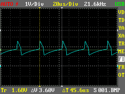
The measured r06aâs fundamental 2272 OSC frequency (at pin 15) is nominally 21.6kHz, yielding a cycle (represented by âÎąâ) of 45.6Îźs. See Figure below. Per the Princeton Technology datasheet, for the PT2272 to decode correctly the waveform that was received, the oscillator frequency of PT2272 must be 2.5~8 times that of the transmitting PT2262. Measurements of the output of r06aâs radio receiver (pin 1 of LM358) show the pulse train transmitted by the key fobâs PT2262 â see Figure 6, above. Measurements of that waveform show that a short âhighâ is nominally 440Îźs long. The specification says that a short âhighâ is 4Îą long so this would, at first glance, seem to be incorrect since 4 * 45.6Îźs = 182.4Îźs. However, recalling that the 2272 OSC is 2.5~8 times that of the transmitting PT2262 then (2.5 * 4) * 45.6Îźs = 456Îźs. This is within my measurements â my measured nominal value of a short âhighâ being nominally 440Îźs long was derived by averaging measurements from 404Îźs to 476Îźs. Therefore, with my PT2272 chipâs Îą is 2.5 times its OSC frequency. This tells us that the chart in the PT2272 Princeton Technology datasheet timing chart actually reflects 2262 data, not that of the 2272. So, I modified the chart for a more correct story. See Figure 7, below.
As can be seen in Figure 7, above, a single data bit that represents a high, low or float state transmitted by the 2262 consists of two pulse cycles, the duration (short or long) of each of the two pulses representing the bitâs value:
Short/short = low (0), long/long = high (1), short/long = float (f). If you decode the waveform received from my 2262 fob transmitter youâll see that it decodes to exactly what is encoded in the fob, as we would hope would be the case â FLHHHLFF (A0 is leftmost address digit) and D0 is the rightmost data digit.
The two pulses are 32 Îą long in total. Given that my PT2272âs Îą is 114Îźs the total duration of one bitâs two pulse cycles should nominally be 3.65ms. My actual measurements ranged from 3.598ms to 3.679ms so measurements are tracking the specification.
Thatâs all for now.

