
| 22-11-2013 (3507 ) | Categoria: Audio |
There is a large number of things that amazes me on an almost daily basis.  To wit: a local mom and pop radio station called me because they couldn’t get their computer program to work right.  I decided that I’d give them an hour or two, in exchange for my hourly labor rate, and see if I could fix their problem.  The issue at hand was loud hum and other noise on the input source.  I knew before I even looked at it that the likely culprit was a ground loop.
It was worse than I imagined, with several unbalanced and balanced feeds improperly interconnected, line level audio going to a microphone level input and so forth.  I explained to the guy about putting line level into a mic level input, something akin to plugging a 120 volt appliance into a 240 volt outlet.  Improperly terminated balanced audio nullifies all of the common mode noise rejection characteristics of the circuit.
In any case, there are several ways to go from balanced to unbalanced without too much difficulty.  The first way is to wire the shield and Lo together on the unbalanced connector.  This works well with older, transformer input/output gear, so long as the unbalanced cables are kept relatively short.
Most modern professional audio equipment has active balanced input/output interfaces, in which case the above circuit will unbalance the audio and decrease the CMRR (Common Mode Rejection Ratio), increasing the chance of noise, buzz and so on getting into the audio. In this case the CMRR is about 30 dB at 60 Hz.  Also, newer equipment with active balanced input/output, particularly some brands of sound cards will not like to have the Lo side grounded. In a few instances, this can actually damage the equipment.
Of course, one can go out and buy an Henry Match Box or something similar and be done with it.  I have found, however, the active components in such devices can sometimes fail, creating hum, distortion, buzz or no audio at all.  Well designed and manufactured passive components (transformers and resistors) will provide excellent performance with little chance of failure.  There several methods of using transformers to go from balanced to unbalanced or vice versa.
Using a 600:600 ohm transformer is the most common.  Unbalanced audio impedance of consumer grade electronics can vary anywhere from 270 to 470 ohms or more.  The 10,000 ohm resistor provides constant loading regardless of what the unbalanced impedance.   In this configuration, CMMR (Common-Mode Rejection Ratio) will be 55 dB at 60 Hz, but gradually decreases to about 30 dB for frequencies above 1 KHz.
A 600:10,000 ohm transformer will give better performance, as the CMMR will be 120 dB at 60 Hz and 80 dB at 3 KHz, remaining high across the entire audio bandwidth.   The line balancing will be far better into the high impedance load.  This circuit will have about 12dB attenuation, so plan accordingly.
For best results, use high quality transformers like Jensen, UTC, or even WE 111C (although they are huge) can be used. ¬†I have found several places where these transformers can be ‚Äúscrounged,‚ÄĚ DATS cards on the old 7300 series Scientific Atlanta satellite receivers, old modules from PRE consoles, etc. ¬†A simple audio ‚Äúbalun‚ÄĚ can be constructed for little cost or effort and sound a whole lot better than doing it the wrong way.
A brief list, there are other types/manufactures that will work also:
| Ratio | Jensen | Hammond | UTC |
| 1:1 (600:600) | JT11E series | 804, 560G | A20, A21, A43 |
| 4:1 (10K:600) | JT10K series | 560N | A35 |
Keep all unbalanced cable runs as short as possible.  In stereo circuits, phasing is critically important, so pay attention to how the transformer windings are connected.


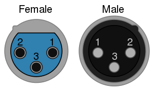
EIA Standard RS-297-A describes the use of the XLR3 for balanced audio signal level applications:
 |
|
| Pin | Function |
|---|---|
| 1 | Chassis ground (cable shield) |
| 2 | Positive polarity terminal for balanced audio circuits (aka "hot") |
| 3 | Negative polarity terminal for balanced circuits (aka "cold")[15] |
Prior to the introduction of this standard, the wiring of pins 2 and 3 varied. The pin 2 "hot" and pin 3 "cold" convention was typically used by European and Japanese equipment manufacturers, but American companies used pin 3 "hot" and pin 2 "cold". This caused problems when interconnecting equipment with unbalanced connections. The pin 3 "hot" convention is now obsolete but is still found on vintage equipment.[16] Pin 1 has always been ground and/or shield if the cable is shielded, and many connectors connect it internally to the connector shell or case.
Although covered in industry technical standards,[17][18] there is still some disagreement on the best way to handle the use of pin 1 for grounding (earthing). The main controversy is whether the shell of the connector should be connected to pin 1 or the shield, or left floating. AES standards mentioned above recommend that shells of cable-mounted connectors should never be connected to pin 1 or the shield, because inadvertent contact of the shell with another grounded surface while in use can create unwanted current paths for fault current, potentially causing hum and other noise. On the other hand, equipment containing active circuitry should always have pin 1 connected to the conductive enclosure of the equipment as close as possible to the point where the signal enters the enclosure. The argument centers around the radio frequency shielding provided by the shell of the connector, which may be reduced if it is left floating. An alternative solution is to connect the shell to pin 1 and the shield through a small value capacitor, providing RF shielding but allowing very little audio-frequency current to flow. This capability can be built into a fixed jack or a cable terminated with XLR connectors.
The standard signal flow for audio in XLR connectors is that the output is a male connector and the input is female. In other words, the pins on the plug point in the direction of signal flow. This is the opposite of power connector standards which normally use female connectors for outputs, a convention influenced by the need to prevent accidental contact with dangerous voltages. However, the voltages of microphone and line level audio signals are not hazardous. The male XLR is usually incorporated in the body of a microphone.
Since equipment often requires an input on a TRS phone jack or an XLR connector, Neutrik and Amphenol offer several models of combination connector that accept both XLR and 0.25 inch TS or TRS phone plugs.
The 3-pin XLR is used as extreme low voltage power connector.[citation needed]
| Use | pin 1 | pin 2 | pin 3 | note |
|---|---|---|---|---|
| console light <1990 | chassis shield | 12 Vac black | 0 Vac white | White connected to center tab extreme low voltage transformer. |
| console light >2000[19] | chassis shield | 12 Vdc red | 0 Vdc black | 0 Vdc shunted to chassis at rectifier. |
| camera Arri | 0 Vdc | 24 Vdc | n.c. | |
| camera Panavision | 24 Vdc | 0 Vdc | n.c. | |
| charger | 28 Vdc red | 0 Vdc black | =2 | Pin 3 signals motor off. Male connector at charger. |