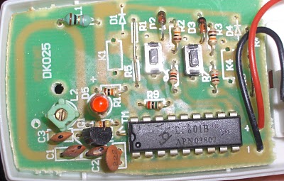
I popped the original remote open to see what I was dealing with. After some research I concluded that LP801B is a PT2262 clone which is a remote control encoder chip. Has a few address and data pins and generates a signal on the output pin based on the configuration of those at the time the enable pin is connected to ground.
At first I didn't think much of it and ordered some PT2262s and made a PCB which is basically a clone of the original remote adapted for components I had lying around (or just stupidly large pads where I had no idea what I was going to use when I made the board)
Not being patient enough however I started looking around to see if anyone's emulated this chip on a microcontroller before. Turns out, several people did.
So I took the code at http://www.mikroe.com/forum/viewtopic.php?f=13&t=10832 and ported it over to BASCOM for the ATTINY13.
I think that code has a bug though as the logic low component of the syncbit should be 31 times the short-pulse duration according to the datasheet not 7. (He's basically divided the datasheet units by 4 in case anyone actually looks into this) The decoders may not care as It seems to have worked for him. When I got mine to work I was using the datasheet-correct count so I didn't test with that. It took several modifications to my original board to get it working with the attiny. Had to put in 3 zeners as the PT2262 operates directly from 12v which the attiny can't do. I actually fried an ATTINY2313 the first time around because I forgot the two selector/power buttons that were still at 12v. If I knew in advance that I'd be able to do this I would've designed a much smaller board..
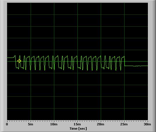
I was trying random numbers for the pulse duration and randomly tuning the white variable capacitor but with none of the parameters actually being correct this method was never going to work. After some wasted time I caved and connected the original remote's encoder chip data output pin to the microphone input of my netbook.
Then with the cool Soundcard Oscilloscope to which I could adapt my pulse duration.
At this point I tested my board and while tuning the variable cap it suddenly became dark in the room :) It took a few more iterations to get the delay "just right" but now it works perfectly.
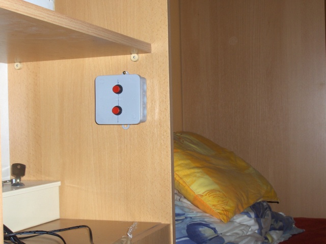
I put it in a small electrical box with 2 push-buttons and installed it in an easy to reach location from the bed.
Some component leg that I forgot to cut (probably a resistor) must have punctured the battery wire though as it drained to 10v by that night and since the circuit is basically open when none of the buttons are pressed that shouldn't happen at all. I did find a puncture mark on the positive lead so that must have been it.. damn. After reseating the board in the box and making sure the battery wires don't pass under any component legs it hasn't happened again.
Project files:
Board
Very large. But the (somewhat smaller, by about 20%, still fairly large) version is on the browsing/printing PC upstairs and I'm too lazy to get it :) Note below on the jumper blocks:
[1] [2] [3]
No connection: FLOAT bit
1+3: Bit 0
2+3: Bit 1
1+2: Short out the battery
And that this PCB is for the PT2262 (and clones) so it needs modifications to be used with an AVR. At least 1 5.1V zener for the CHIPPWR and 1 per button.
The board runs off a 23A (12 volt) stack battery. Running from lower voltages may be possible but the RF circuit definitely needs to be retuned.
Schematic
The seemingly unconnected wires from the diodes on the data pins are actually connected to CHIPPWR.
PT2262 emulation code in BASCOM
001 |
$regfile = "attiny13.dat" |
004 |
Declare Sub Sendbit(byval A As Byte) |
017 |
Dataout Alias Portb.2 |
020 |
Config Dataout = Output |
021 |
Config Portb.0 = Input |
022 |
Config Portb.1 = Input |
100 |
Sub Sendbit(a As Abyte) |