

| 30-05-2014 (4387 ) | Categoria: RemotePark |
designed by Peter JAKAB in December, 1999
improved in Jan. 2001
NOTE for beginners: PICs are general purpose microcontrollers which have to be programmed before you can use them in the actual circuit! Check out this link to learn more.
If you are looking for walkie-talkie or RF circuits, please check here (this page has nothing to do with walkie-talkie circuits).
| I finally got some small 433MHz radio transmitters and receivers and I needed an encoder/decoder circuit to make use of them for controlling equipment remotely. One could realize this by using Motorola MC145026-8 integrated circuits as well, but they need space and a few external components that must be calibrated by the user. Not to mention the challenge of creating an encoder/decoder by myself in software.
The encoder/decoder parts are to be connected to a transmitter/receiver module which takes care of the transmission of digital signals by radio or infra waves. The communication signal format is designed to be used for radio transmission (it has a constant 50% signal/silence ratio), but it can work with infrared devices as well. The transmitter has a varying number of buttons and sends the states of these inputs to the receiver. The receiver device decodes the message and sets the outputs accordingly. There are two protocols in the sources: the older version V2 represents digital 0 and 1 as different frequency pulses (800 and 1600 Hz), while the newer V4.0 outputs standard Manchester code (400/800 Hz). I recommend using the Manchester versions as the max. generated frequency is lower and the reception is more stable even with low speed or timing-inaccurate transmission channels. As the source is available, you can combine the various parts of code toghether to design a system that fits your needs. Please note that all the devices have a device ID, which has to be the same between a transmitter and a receiver! This is not the PIC ID stored in a separate area of PIC but a software ID stored in the program area. It is encoded in every transmitted packet and checked to match by the receiver to identify matching transmitters & receivers. |
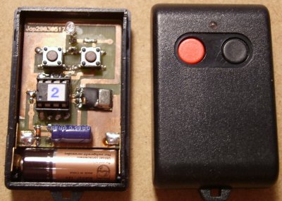 RF transmitters with the PIC encoder |
All the files are provided here without any warranty. Please verify operation first by compiling the sources for flash parts. The sources you see here are proven working in several devices, still if you would find an error, please notify me!
There are two different methods for encoding/decoding channel information:
This version, when powered on, continously transmits the states of all inputs. I recommend installing an ON/OFF switch for the mtx-014 transmitter. The receiver will decode the messages and adapt the output states accordingly. The "TV" TTL output shows that the transmitter is turned ON and signal reception is good. When the signal is absent for about a second, all outputs will go low and the TV out will be cleared. Files are mtx-014 and mrx-009. The transmitter has an ADJUST mode which outputs a periodic signal to calibrate the transmission channel on an oscilloscope. To enter this mode, press TC2 while turning the power on.
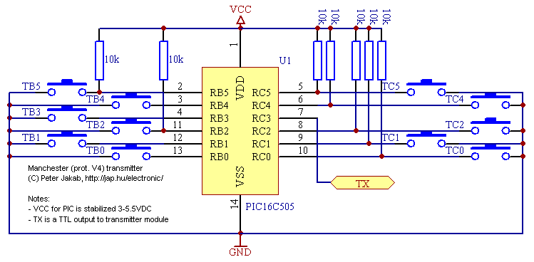
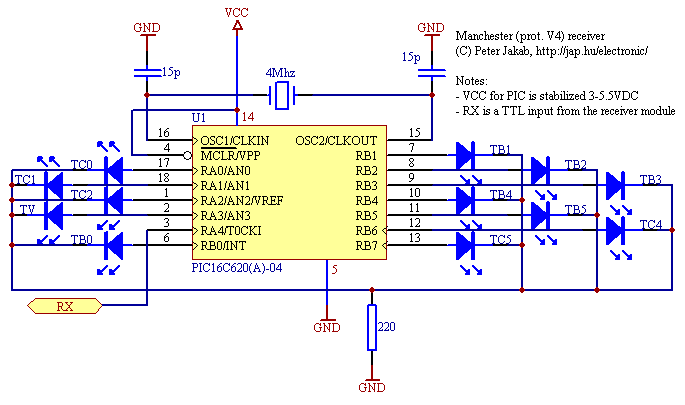
When powered on, in idle mode it emits a 800 Hz synchronization header signal. Otherwise, it will transmit a message like the V2 transmitter described below (tx-002). The hardware is also the same as with the V2 version (without the need for the diodes). Files are mtx-013 and mrx-007.
This one is designed to be a low power transmitter device with one button. It will transmit a message with the number of times the button is pressed. The unused inputs are used to drive a LED and turn on OSC before transmission (it can be used for ASK modulation). You'll have to face the challenge to code the receiver as it is not yet ready. Sorry, no schematic is available for this version. File is mtx-015.
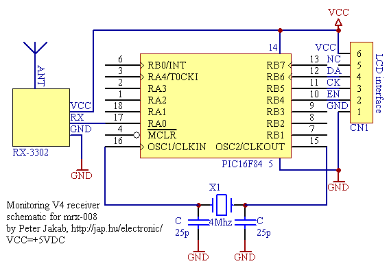
| This code is used to display the receiver code errors and buffers on an LCD display. At least 2x16 line is needed. The LCD library drives a special 3-wire serial interface designed by Myke Predko. File is mrx-008. The LCD interface is described here. | 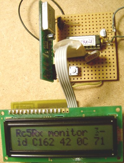 monitoring V4.0 receiver LCD |
Encoder is a small, low power device which has 5 buttons and by pressing one or more keys it transmits a message continously. The transmitted message contains the state of all buttons and it is sent in each message. On the receiver part, for all transmitter buttons there exists a corresponding output pin which will go high for the time the button is being pressed on the encoder. Files are tx-003 and rx-003. I suggest that you consider using the newer V4.0 devices or change a few lines to reduce speed to 400/800 Hz (transmitter delay loop and receiver timer prescaler).
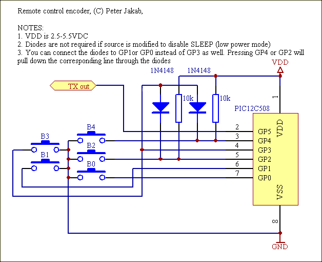
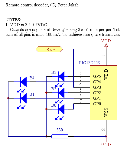 receiver input is GP3. To reverse the receiver polarity (HIGH on transmitter OFF), uncomment the define RX1010 in the source. Other pins are outputs and capable to drive LED diodes or transistors with relays.
| By my own experiences I realized that one can't easily design & build these at home. High frequency circuits need special expertise and equipment so I recommend that you buy a working PCB module. I used the following devices: HX1000 transmitter (operates on 3.0-5.5VDC), RX1010 receiver (max. 3VDC) from RFM and small ready-made PCB panels: a receiver operating on 5VDC (RX3302) and a transmitter (9VDC). The PCB transmitter had a 300 usec wake-up which was too much at 1600 Hz with the V3 protocol. The RF modules are available from a lots of companies. Here is a list of companies from Oricom:
Laipac, Linx, IMST, Glolab, Semelab, Sage, Axonn, Lincast, Abacom, Ramsey, Orbit, Innomedia, RF Innovations, Radiometrix, QKWElec, Temic, Lemos, Unilink, TrueBlue, Parallax, Computronics, VideoComm, Rentron (schematics), RFM |
|
 434M RF modules: RF-EZ STM transmitter, TM01DS transmitter, 15-980TX transmitter |
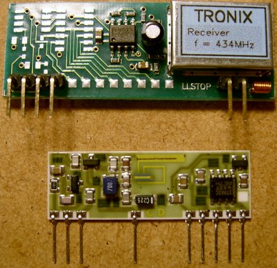 434M RF modules: Tronix RX-3302 receiver, Telecontrolli RR8-434 (max 3.3VDC!) receiver |
 
If you don't have access to ready-made RF modules or want to build an infra version, please check my infrared circuits page. You can easily build these modules yourself.
I developed these programs on the PIC16f84 or PIC16f628 and when everything worked OK, I rewrote the programs for the OTP 12c508, 16c505, 16f620a devices. Use these files at your own risk (especially the compiled HEX binaries), please note that they are provided without any warranty.
| description | transmitter code | TX device | receiver code | RX device | default ID |
| 11-channel V4.0 transmitter and receiver | mtx-014 HEX |
16c505 | mrx-009 HEX |
16c620a | 9ae9 |
| 5-channel V4.0 transmitter and receiver | mtx-013 HEX |
12c508 | mrx-007 HEX |
12c508 | 9ae6 |
| one-button V4.0 transmitter | mtx-015 | 12c508 | c14e | ||
| monitoring V4.0 receiver | mrx-008 | 16f84 | 9ae9 | ||
| experimental pin-selectable address V4.0 receiver | mrx-009b |
16c620a | 9ae9 | ||
| five-button V2 transmitter and receiver (old) | tx-003 HEX |
12c508 | rx-003 HEX |
12c508 | c1062864f14e |
| version | bit0 encoding | bit1 encoding | error codes |
| v2 | 1600 Hz (312 us H, 312 us L) |
800 Hz (625 us H, 625 us L) |
0 = OK 1 = error receiving byte 2 = timeout 3 = checksum error 4 = devid mismatch |
| v3 | 800 Hz (625 us H, 625 us L) |
400 Hz (1250 us H, 1250 us L) |
|
| v4.0 | 800 Hz (625 us H, 625 us L) |
800 Hz (625 us L, 625 us H) |
0 = OK 1 = illegal startbit 2 = signal too long 3 = signal too short 4 = no mid-frame transition/out of sync 7 = byte-ending bit1 missing 8 = byte-ending bit0 missing 9 = header too long 10 = header too short 12 = checksum error 13 = devid mismatch |
Q: How to compile the sources for FLASH parts?
A: Delete and modify lines according to this table.
| delete lines | modify lines |
| #define C505 #define C508 |
;define F84 to #define F84 |
| #define C620 | ;define F628 to #define F628 |
Additionally, the lines translating I/O pins to buffer data may need modifications to make use of the maximum number of available pins, because FLASH parts have a different count of I/O pins.
Q: How to make V4.0 sources go faster?
A: By default, V4.0 sources use a 625 usec half frame delay, this means that your channel must be able to transmit 400-800 Hz frequencies. If you go higher, channel requirements also get stiffer. The lines containing the timing information are:
| meaning | line | example modification |
| transmitter code half frame delay (625 usec) |
delayconst EQU .202 |
delayconst EQU .20 |
| receiver code frame tolerances (min half frame, max half frame+min one frame, max one frame) |
min_t EQU .34 min_2t EQU .104 max_2t EQU .174 |
min_t EQU .3 min_2t EQU .10 max_2t EQU .17 |
By adjusting these values linearly, you can make the code go at your desired rate, slower or faster. Examples show a ten times faster modification. If you want a simpler way or a further speed-up, you can use a faster clock instead of the default 4MHz. But you pay for the clock speedup with two pins on the transmitters, because you can get a different clock rate with an external xtal connected to the PIC.
Q: How do I compile the V4.0 receiver sources?
A: You need to use a linked project in MPLAB. Please check the FAQ at the PIC page.
_____________________________________________________________________________________
PIC is the name for the Microchip microcontroller (MCU) family, consisting of a microprocessor, I/O ports, timer(s) and other internal, integrated hardware. The main advantages of using the PIC are low external part count, a wide range of chip sizes (now from 5-pin up!) available, nice choice of compilers (assembly, C, BASIC, etc.) good wealth of example/tutorial source code and easy programming. Once bought, the PIC's program memory is empty, and needs to be programmed with code (usually HEX files) to be usable in a circuit.
Q: What can I do with the assembly source code for the PIC microcontroller?
A: First, you need a compiler, which takes the source code in the form of asm (assembly), inc (include), and lkr (linker script) files. You can compile microchip assembly files with gputils or mpasm, part of MPLAB.
(Gputils are command line utilities, mplab is a graphical development environment)
The compiler will output a hex file, suitable for programming into the device. You need a programmer device for that. It is an interface between the computer and the microcontroller. I recommend using the Pickit 2 or 3 this purpose.
Please read the pcbheaven pic pages to get started with compiling code and programming the PIC microcontrollers.
Q: How do I compile a HEX file from multiple source files (linked project or relocatable code) ?
A: Start MPLAB-X, and select file/new project. Select "Microchip Embedded" in Categories and "Standalone Project" in Projects. Click next, select the target microcontroller you see in the circuit diagram (for example, PIC16F628). Click next, ignore Select Header, and click next again. Select "Simulator" in "Hardware Tools" as Tool. Click next, and select "mpasm (version) for Compiler. Click next and enter a project name. Click Finish. Select Window/Projects. In the projects window, use the actual project, and ignore others (if there are any). Right-click "Linker files", select "Add existing item" and add the linker script (*.lkr) to the project. In the projects window, right-click "Source files", select "Add existing item" and add all assembly (*.asm) files to the project. Right-click the actual project name and select "Build". You will see the compilation output in the "Output window".
A: Start MPLAB, and select project/project wizard. Choose the target microcontroller you see in the circuit diagram (for example, PIC16F628). Choose the MPASM toolsuite. Add all assembly (*.asm), header (*.inc) files and the linker script (*.lkr) to the project. Select project/build all. If asked, choose generating "relocatable code", and not "absolute code".
Explanation: There are two incompatible source types for one-file absolute and multiple-file linked projects, you can't write code working for both types. If you want to build modular code which can be combined with other libraries, code must be written in the linkable format, even if it is the only source file in the beginning. But linkable format source must be compiled differently, in two steps: first compiled into an intermediate object format, then linked into a HEX file.
 
Q: Where is all this assembly language documented?
A:You can find the PIC microcontroller instruction set documentation in the microcontroller datasheets at microchip.com. The PIC12, PIC16, PIC18, PIC24, PIC32 families of microcontrollers have different instruction sets. In addition, the general syntax of the code (labels, variables, macros, etc.) is described in the mpasm documentation.