
La vaca cega desconfiada
_FRASE_TOP
| 16-03-2017 (5998 ) | Categoria: Articles |
December 15th, 2012 | Category: Floppy Emu
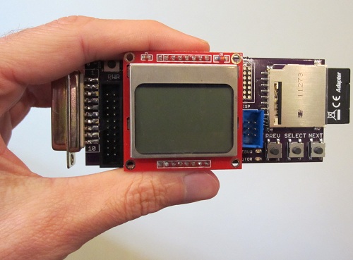
Floppy Emu is a prototype floppy disk drive emulator for vintage Macintosh computers. It emulates 400K, 800K, or 1.4 MB disks, and is compatible with everything from the original Macintosh 128K through the Mac II series and Power Macintosh line.
You can buy a pre-assembled and tested Floppy Emu, or if you’re comfortable with surface mount soldering and have an AVR programming tool, you can build a Floppy Emu at home. Be warned there are several SMD chips with fine-pitch 0.5 mm pin spacing. These can be soldered by hand, but it’s challenging work.
Floppy Emu is released under the Creative Commons Attribution-NonCommercial 3.0 license. You’re free to build one for personal use, or adapt and share the design for other non-commercial projects, but please don’t build a batch of Floppy Emus and sell them on eBay. Now with that out of the way, let’s get started!
Download the Floppy Emu source files
What You’ll Need
Making a PCB
To begin building your Floppy Emu, you’ll need a printed circuit board. Send me an email to ask if I have any extra PCBs available. Otherwise, there are many on-line services that will make these for you, using a set of layout files called Gerbers. You’ll find the Floppy Emu Gerbers in the file archive, in the directory eaglefloppyemugerbers.zip. I recommend using the Dorkbot PDX PCB Order service to get the PCB manufactured. Send them the Gerber files, and they’ll make three copies of the PCB for about $30, with a turn-around time of a few weeks. The guy who runs the PCB service is very helpful if you have questions.
Getting the Parts
While you’re waiting for the PCB, you can locate all the other parts you’ll need to assemble the Floppy Emu. You’ll find a complete parts list in the file archive. The total parts cost (not including the PCB) should be about $40-$50 when ordering in single unit quantities, with taxes and shipping costs.
One of the required parts is a male DB-19 connector, which mates with the Mac’s external floppy port. These can be very difficult to find, and IEC is the only supplier I know that has them. If you can’t find a DB-19 solder type connector, you can still use the Floppy Emu with its alternate IDC20 connector, which is readily available from electronics suppliers. With the IDC20, there are several different connection options:
If you don’t already have one, you’ll also need an AVR programmer like the AVRISP mkII.
Assembly
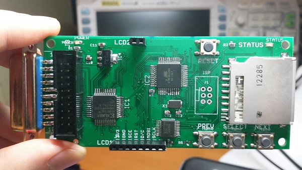
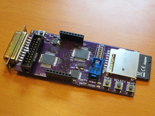
Here’s where things get fun! Refer to the file board-layout.png for placement information, or check the schematics.
The first step is to solder and test the AVR.
The AVR microcontroller should now be functional. You can use AVR Studio to test it out.
If everything is working, the Device ID field should now display 0x1E 0x97 0x05. If it does not, or you encounter an error, review the steps above, then go back and carefully re-check all the solder connections. Do not proceed further until you are able to retrieve the AVR device ID.
The next step is to program the AVR with the Floppy Emu software and bootloader.
These settings should result in the fuse bytes being Extended: 0xFF, High: 0xDA, Low: 0xBF.
Congratulations, the AVR setup is now complete! The next step is the Nokia LCD.
The LCD should now be functional. Connect the Floppy Emu to your Mac, and turn the Mac on. If everything is working, the LCD should show a version number screen, followed by “SD Card init error”.
The SD card reader is next.
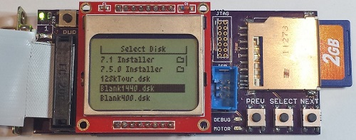
Connect the Floppy Emu to you Mac, and turn the Mac on. If everything is working, the LCD should show a menu listing of the disk images on the SD card.
The final assembly step is the CPLD.
Now it’s time to program the CPLD. The AVR programs the CPLD indirectly, using a firmware file stored on the SD card, so no JTAG tools are needed.
That’s it! Turn the Mac off, then on once more, and you’re done.
Â
Using the Floppy Emu
When it’s turned on, the Floppy Emu scans the SD card for files with a .dsk, .img, or .image extension, and shows a menu of available disk images. Use the PREV/NEXT buttons to select a disk image file, then press the SELECT button to insert it into the emulated disk drive. After the disk is inserted, the LCD display shows the current track number and active side of the drive.
The Floppy Emu expects 400K, 800K, or 1.4MB disk images in either raw format (the .dsk images typically used with Macintosh emulators), or DiskCopy 4.2 .image format. Raw image files support reading and writing to the emulated floppy disk. DiskCopy 4.2 images are read-only.
Floppy Emu supports normal sector-by-sector writing, such as copying files in the Finder, or saving data from within a program. It does not support formatting the emulated floppy, or using it with format-and-write disk copy tools. If you need a blank disk image file, create one on your PC and then copy it to the SD card.
Â
Extending Floppy Emu
The C source code for the microcontroller program is provided in the file archive. You can build it with AVR Studio, generate a new floppyemu.hex and merged.hex file, and load it to the microcontroller using the AVRISP mkII.
The Verilog source code for the CPLD is also provided. You’ll need Xilinx’s free ISE WebPACK to build it. Export an XSVF file, and rename it to firmware.xvf. Then copy the file to the SD card, and load it onto the CPLD as you did before.
Happy hacking!
Read 30 comments and join the conversation| Iohannes Tinctoris - Jerusalem |
| Lumen domus o Annals del convent de Santa Catharina Verge y MĂ rtir de Barcelona - Universitat |
| Ullera llarga vista |
| The Ptolemy Problem |
| Reflexions sobre el tĂtol del Lazarillo de Tormes |
| Barcelona by Wyngaerde |
| Amalfi: InvenciĂł de la bruixola |
| Pedrenyaler |
| Gittern - Giterna |
| La longitud i els eclipsis de lluna -4rt viatge de Colom |
A huge thanks for this! I know it takes forever to do all the documentation to bring others up to speed. Thanks a bunch for doing all that.
I’ve ordered PCBs and parts!
._. Now I have to find someone who knows how to solder for me. Hopefully someone here will get permission to make and sell these on eBay, with credit and a portion of money to the guy who made it.
Looks like I have to get some parts and pcb’s made
versió per imprimir